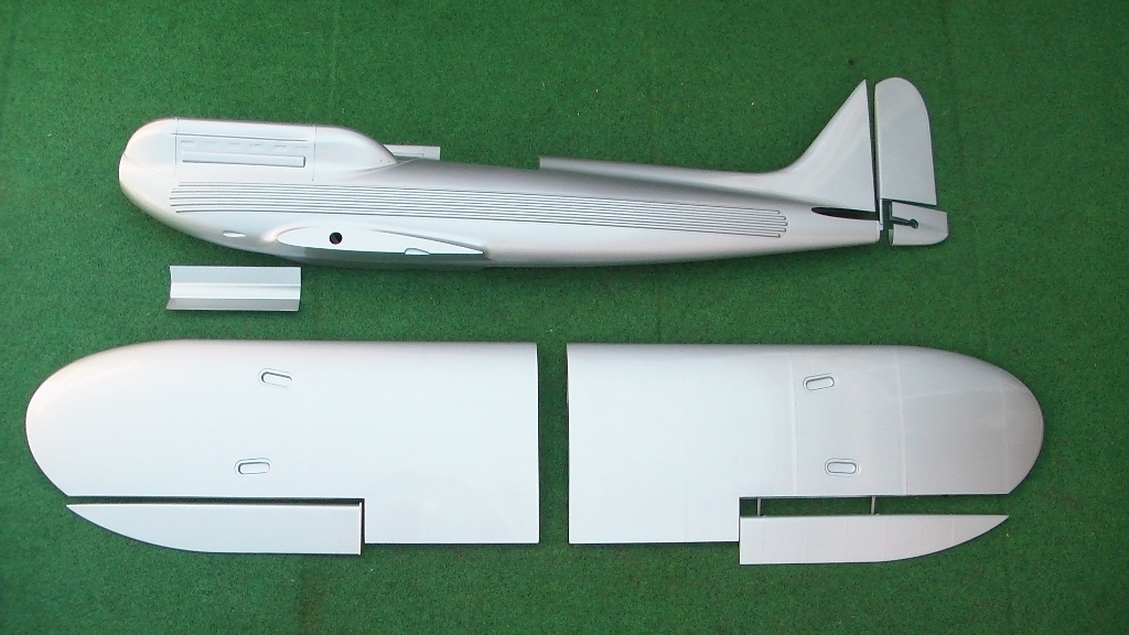
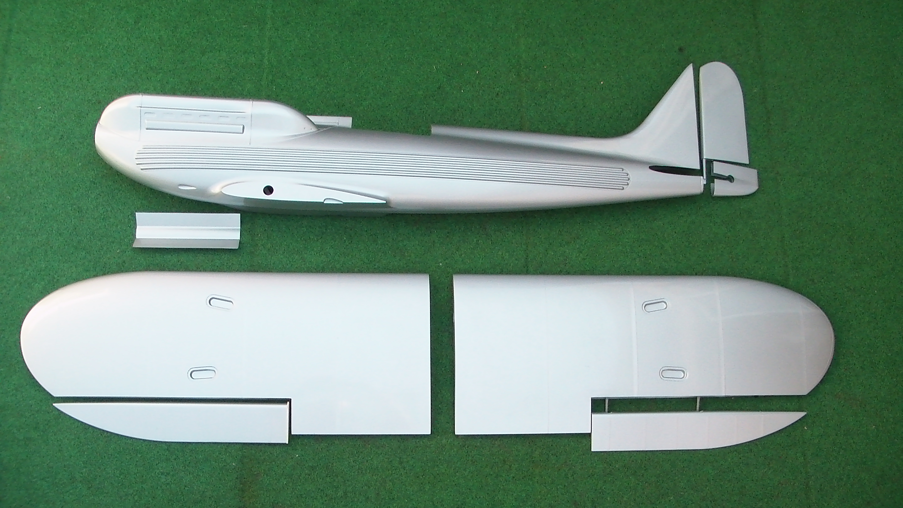
Description
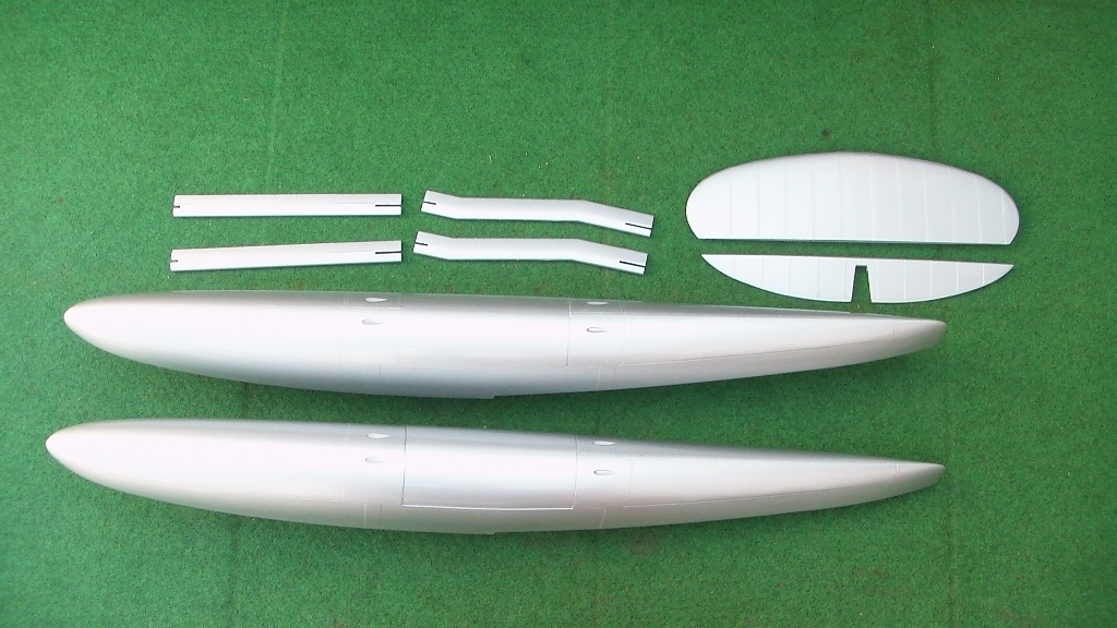
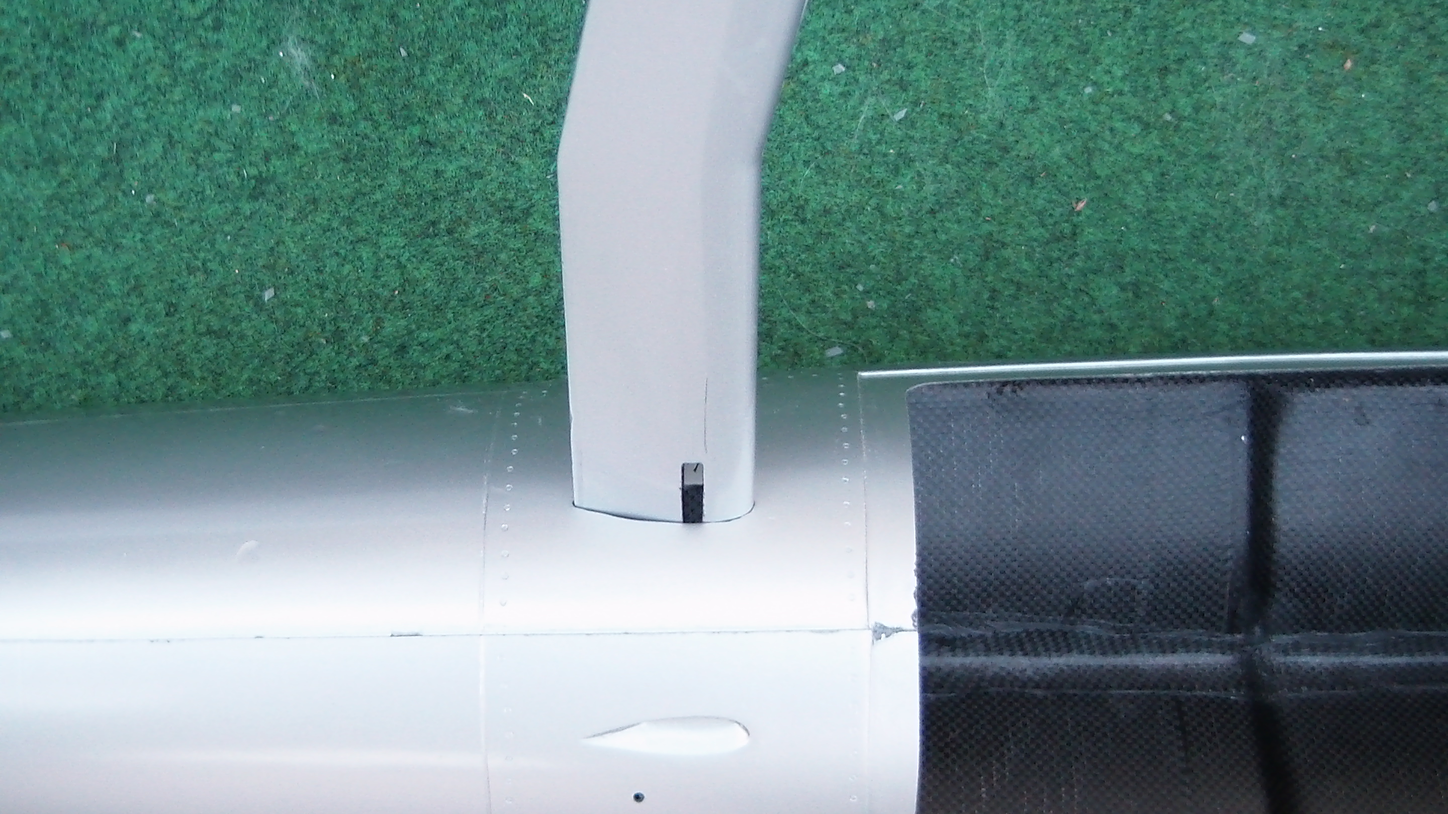
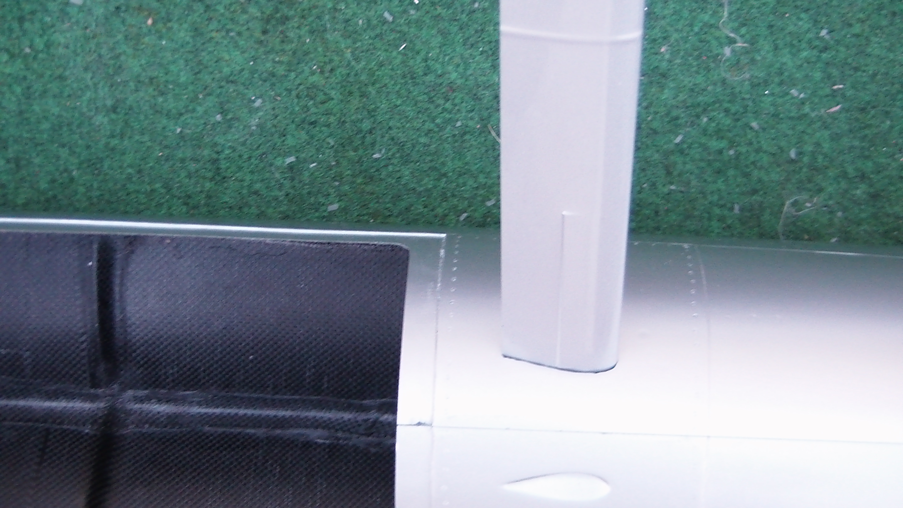
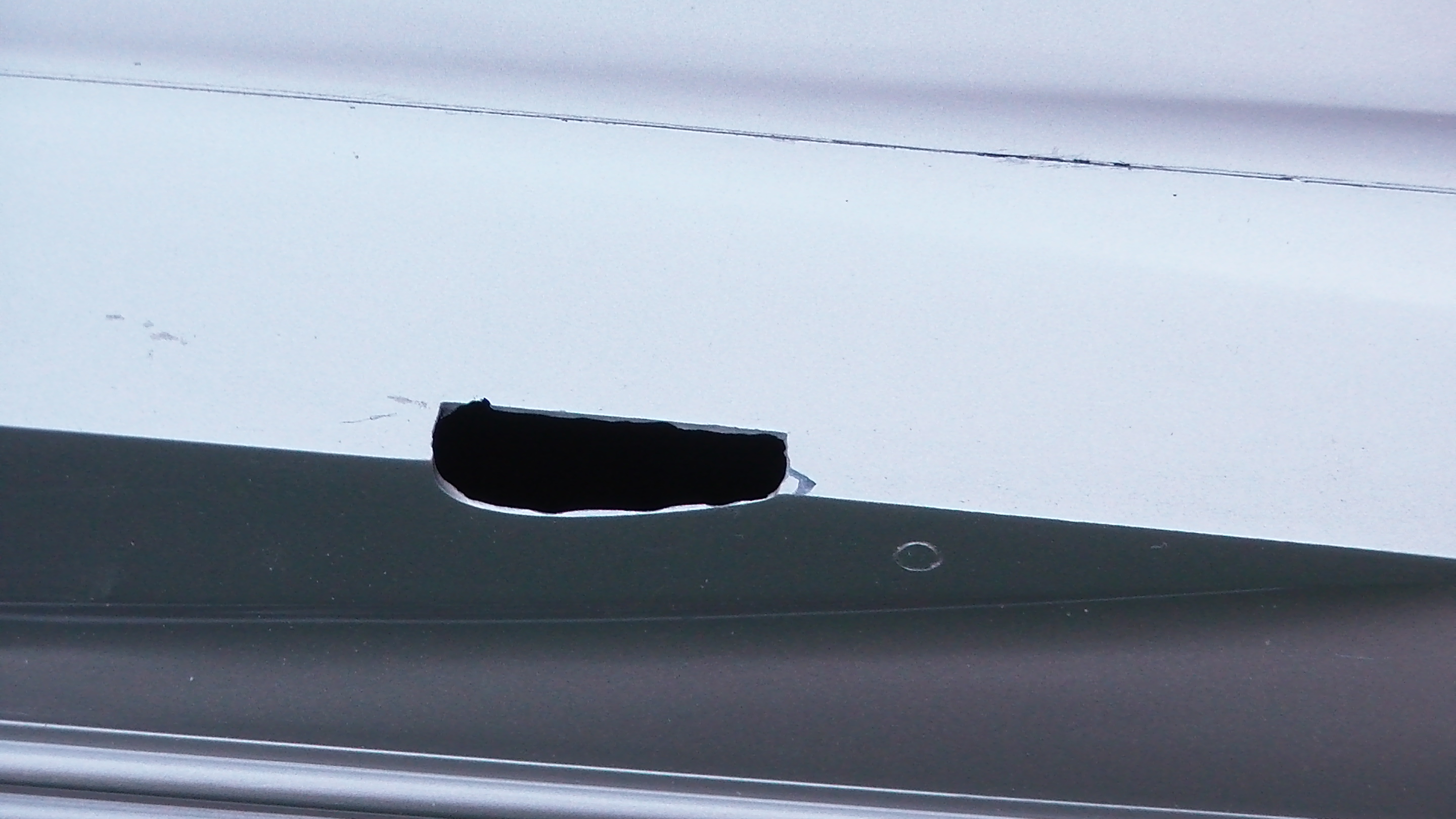
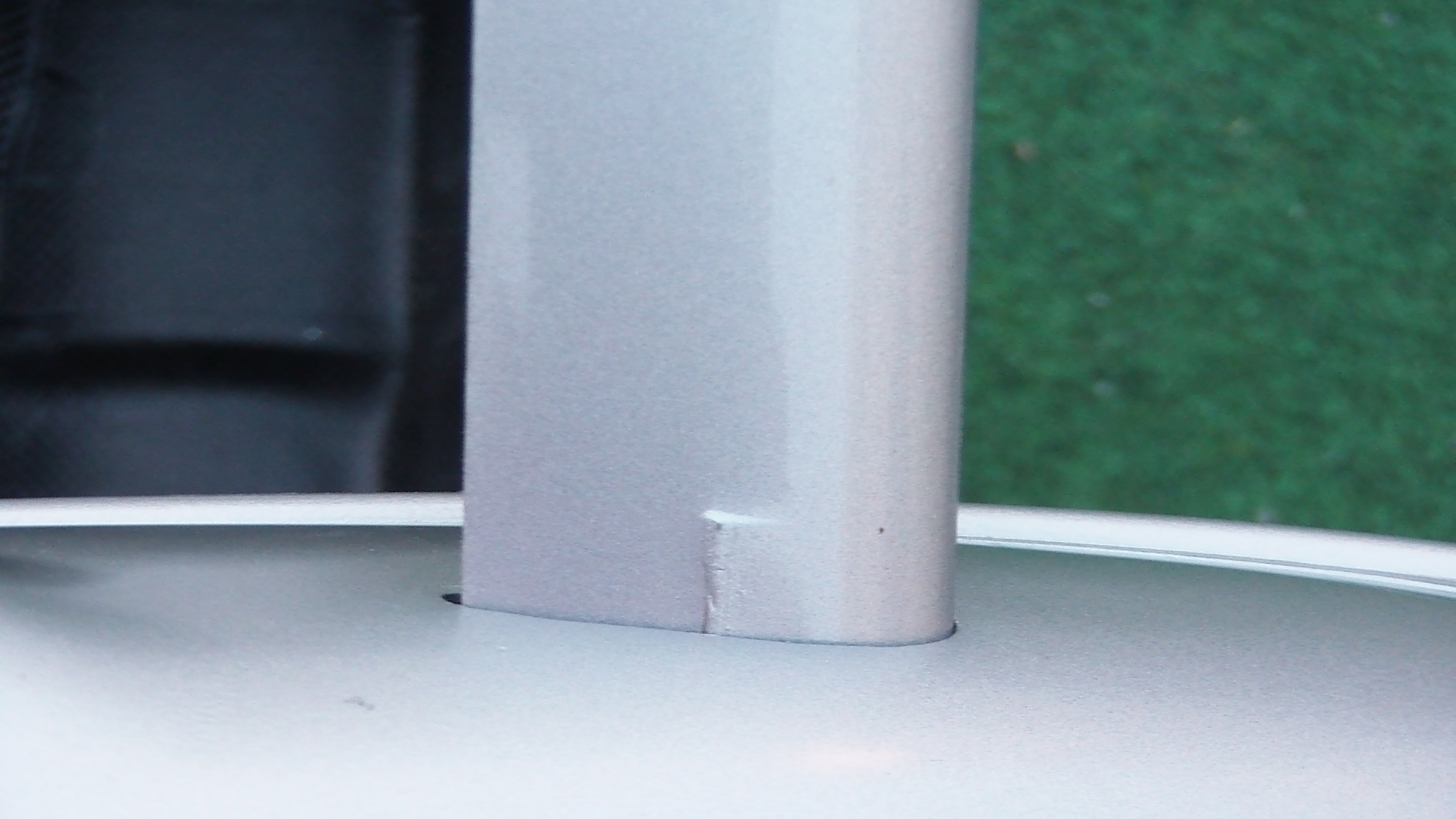
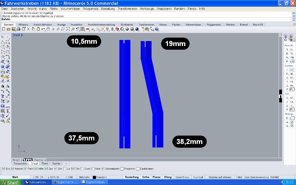
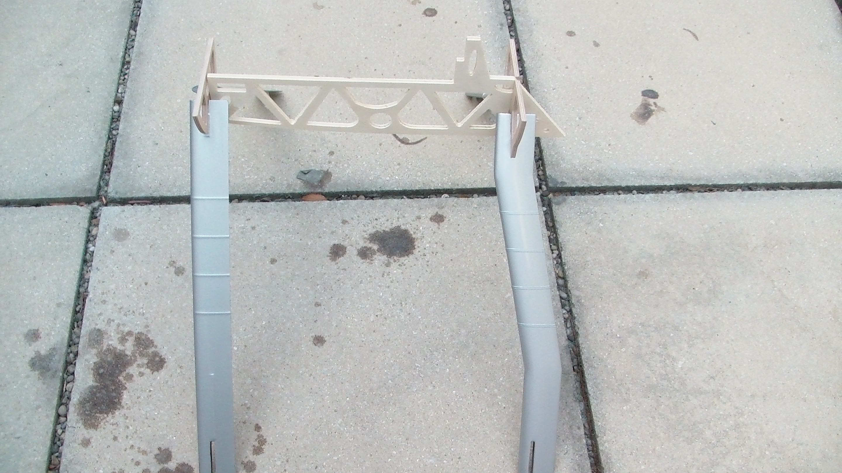
It is best to start milling the openings for the float struts in the fuselage and the floats. Cut out the indicated openings so that the float struts fit with minimal play. In the case of the floats, take care to mill the openings for a left and a right float.Trial fit the float struts, aft and front struts have different dimensions.
The floats have markings for holes to the left and right of the openings for the float struts, into which the eyebolts for the bracing are later glued. Drill these holes with 3mm, 4 holes per float.
Thereafter carefully insert the alu connector through the fuselage. Attach the wings, use caution where to hold the wings while handling since the laminate is thin in the area of the ailerons. Its best to grab the wings on the leading edge.
Check fit of wings on fuselage. The opening for the alu connector in the fuselage must be extended to fit the tube of the alu connector, if necessary the opening in the fuselage should be corrected so that the wings fit flawlessly to the fuselage.
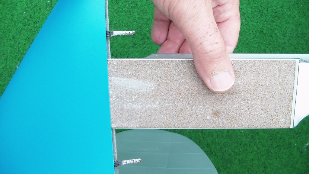
Open the opening in the fuselage for the tube of the alu connector. Ideal for this is a conical rod, wrapped with abrasive paper. Just rotate, do not push back and forth, the laminate could break out.
Then insert the tube, slide the inner structure on and use it as a template for the lock near the trailing edge.Drill with 5mm into the fuselage. The inner structure must overlap the entire length as far as it is at the level of the attachment.
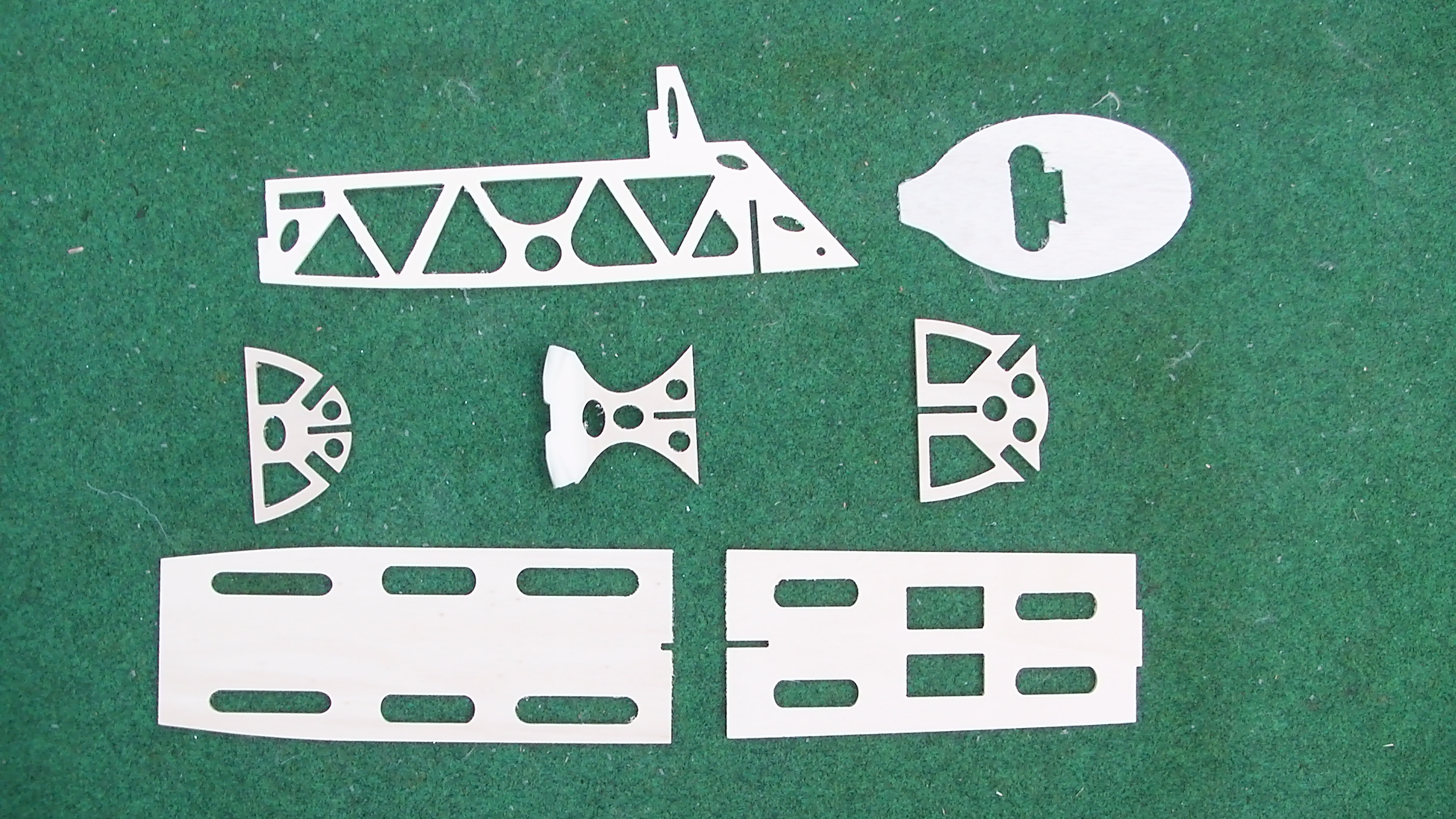
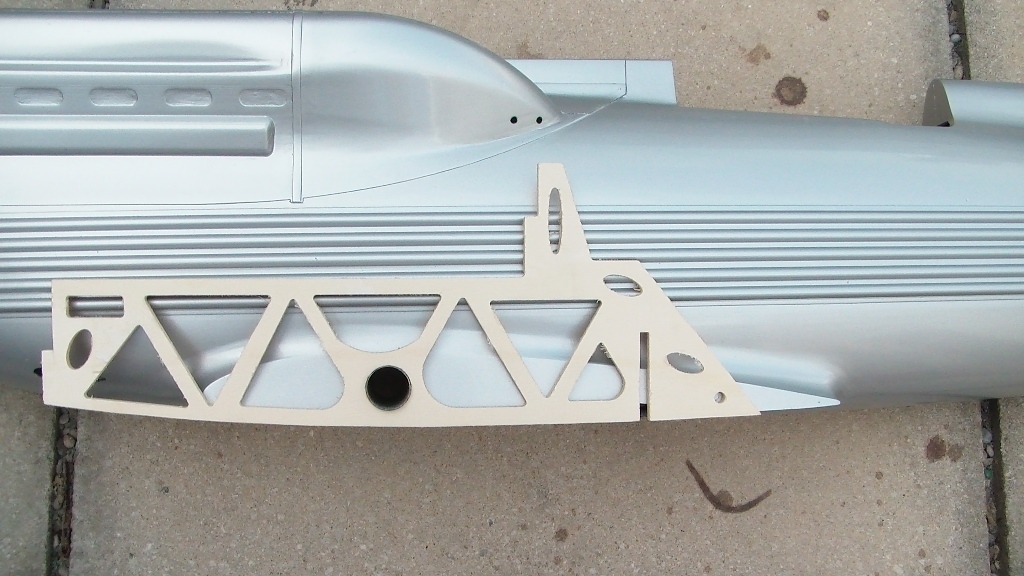
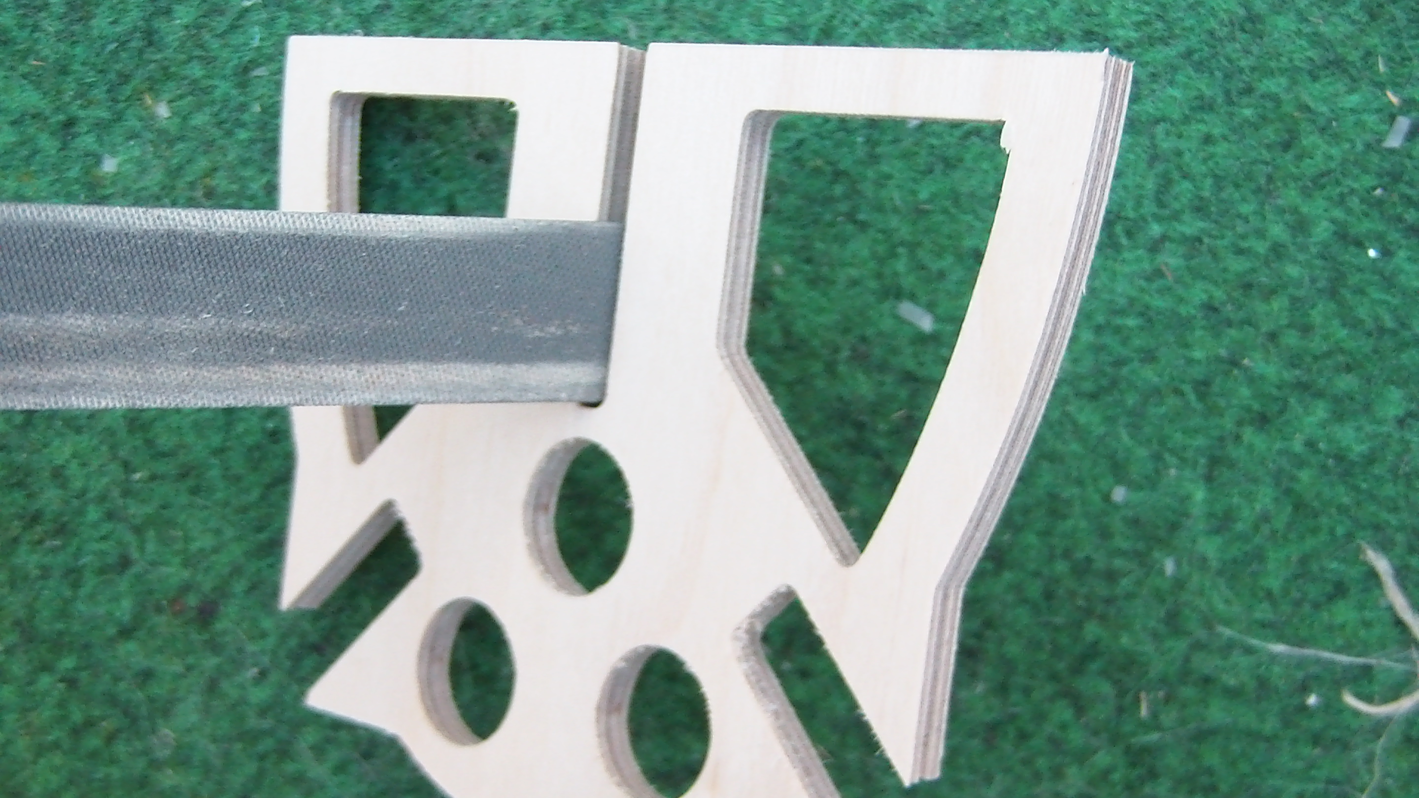
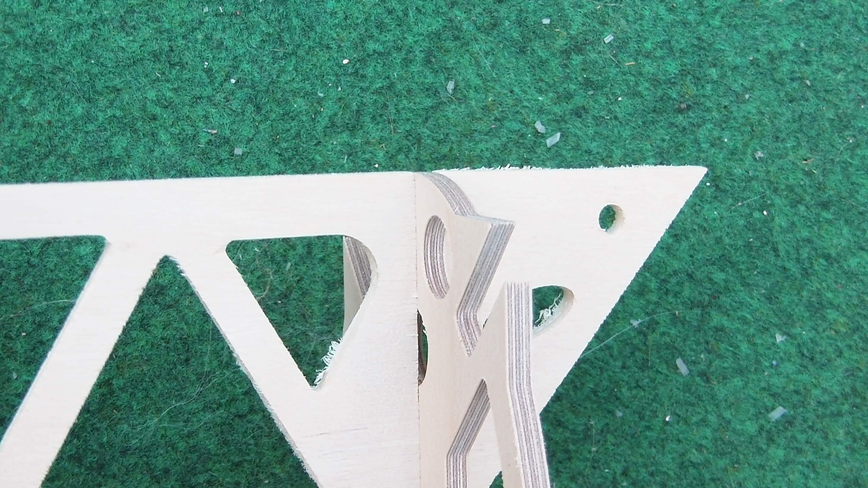
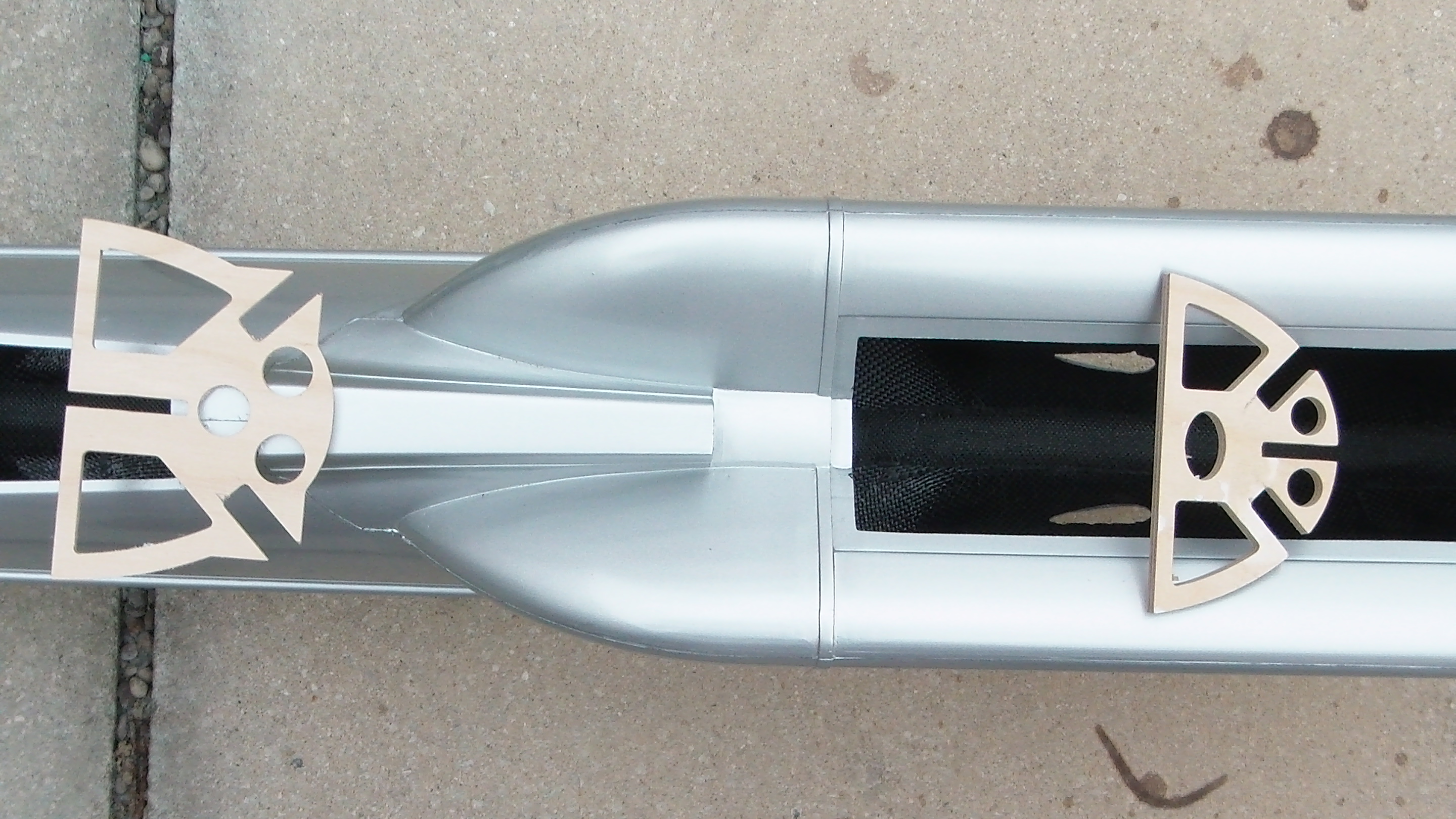
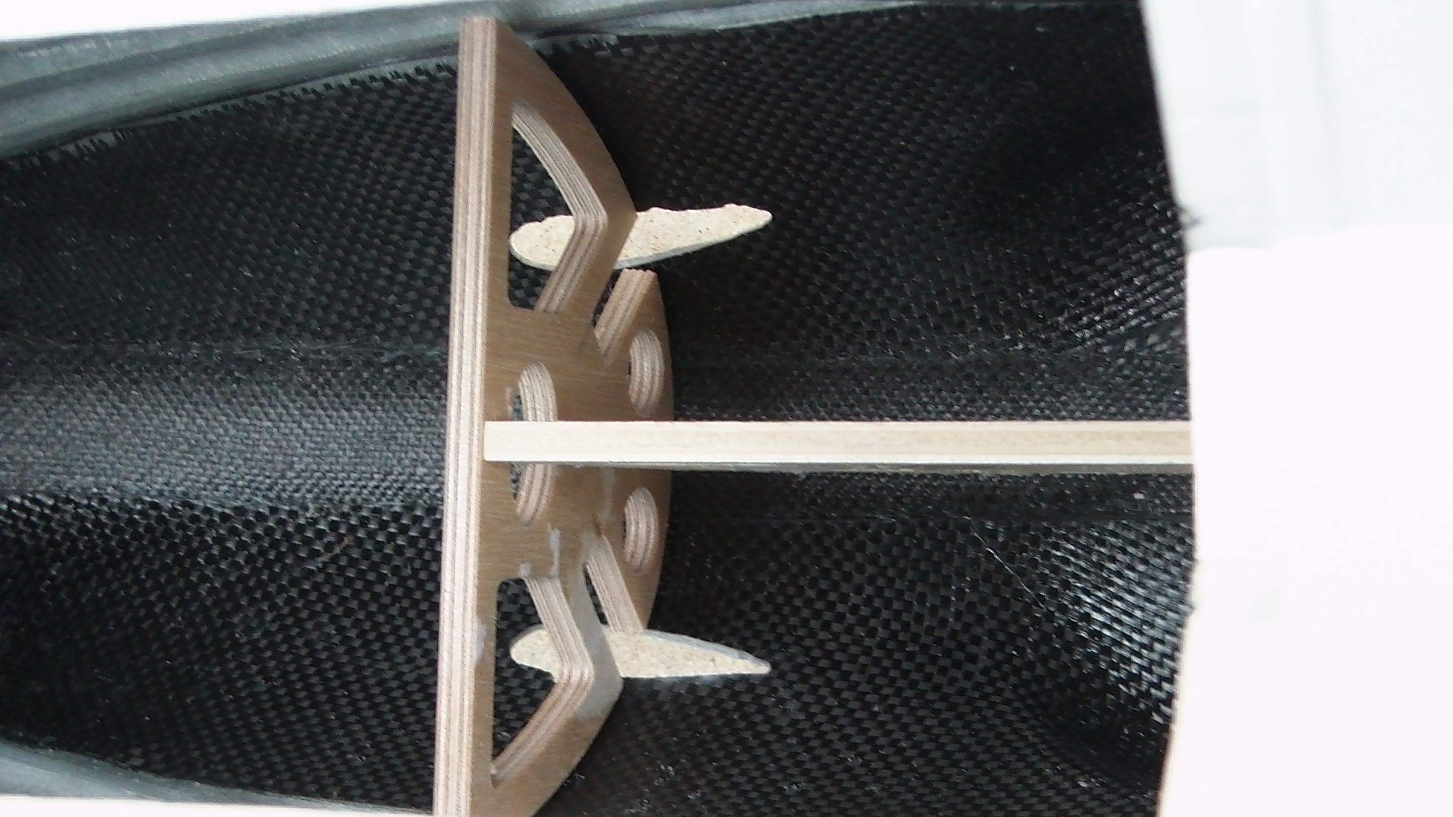
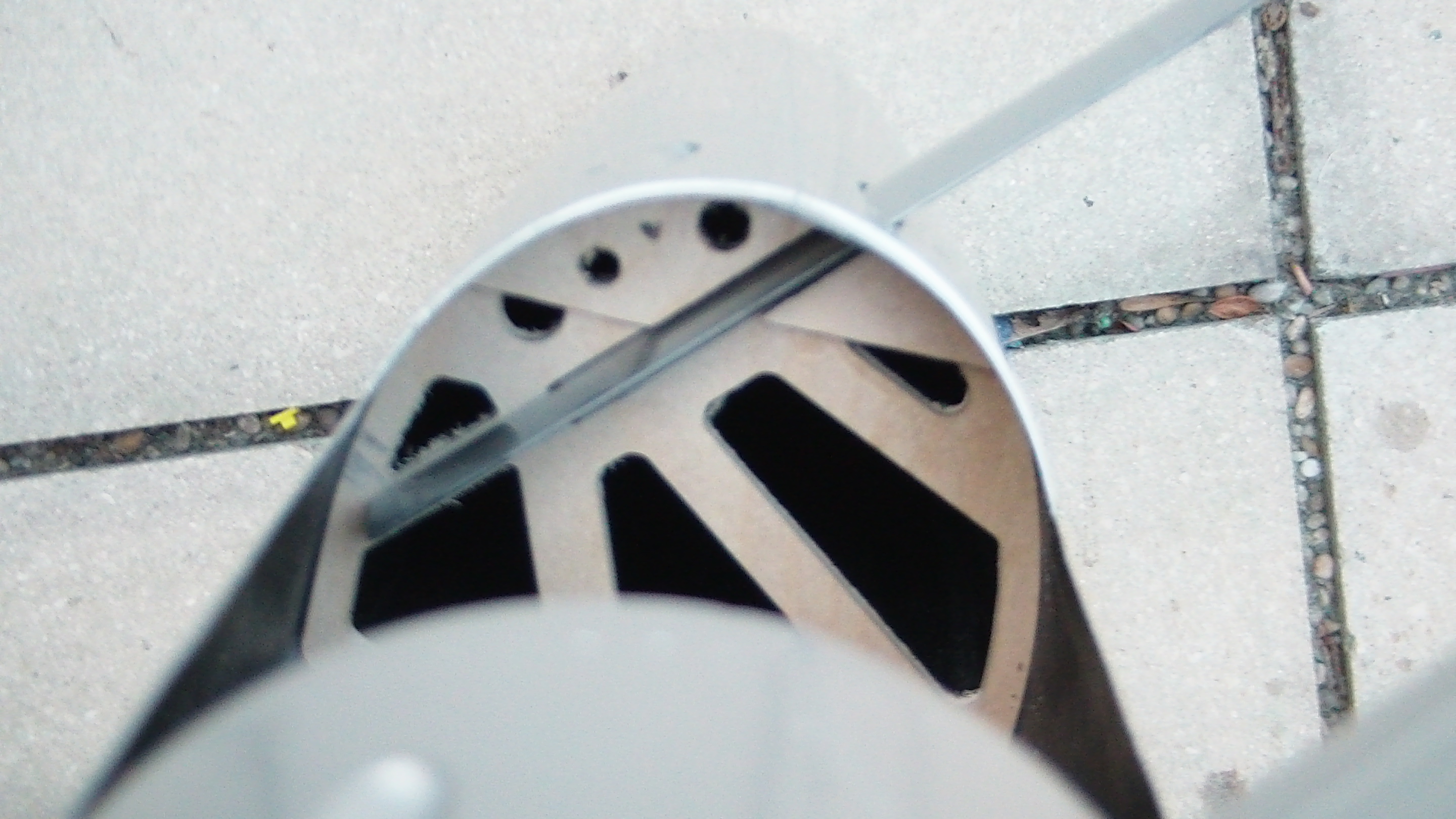
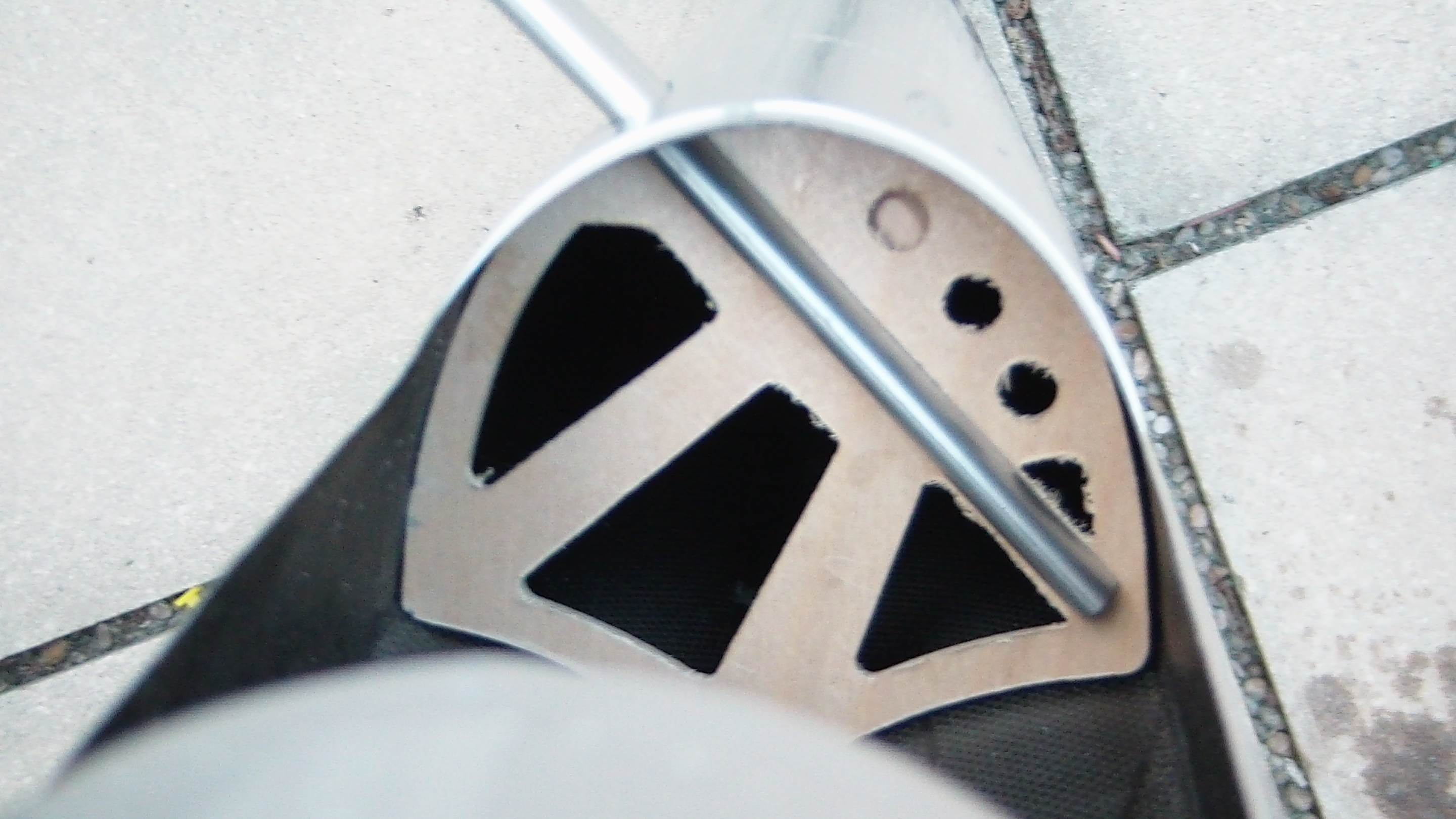
For the wood parts, cut the milling radius in the corners and put it all together. Here in the picture the rear former, it is larger than the front and has jags below.
Assembly must be done without exerting any effort, since it is later done in the fuselage, and the former with their underside must be flush with the inner structure.
Then trial fit the float struts. First, make shure that the length of the slot is as long as shown in the picture.
The width of the slot must be 4mm, if necessary remove material on both sides so that the struts fit into the former of both the fuselage and the floats.
The assembly begins by bringing the former and the inner structure into the fuselage.
Front and aft former:
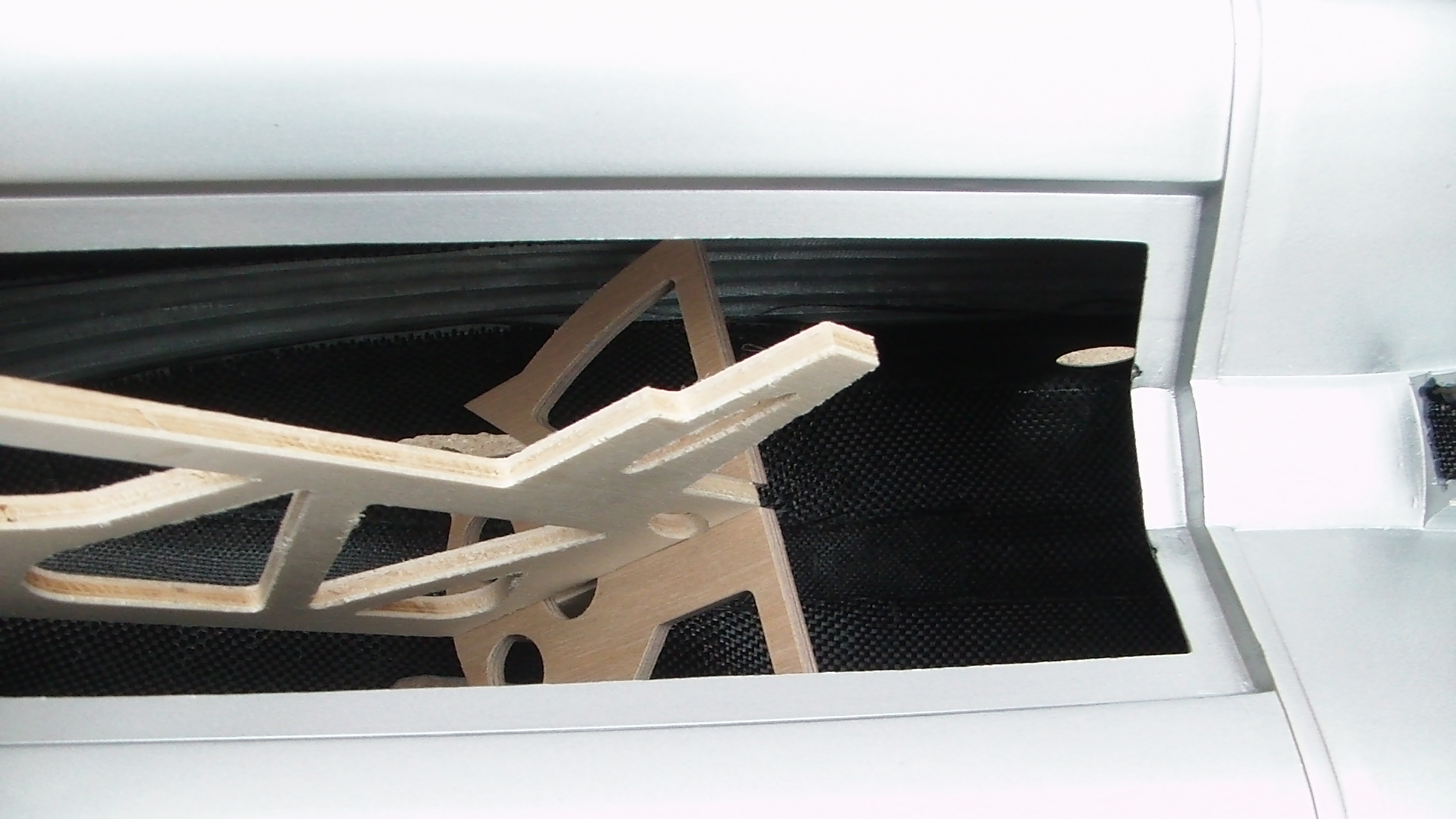
The rear former is inserted through the hatch, the inner structure is placed into the former.
For the time being, do not use an adhesive to make any changes that may be necessary. If the former are glued to the inner structure, they can not be removed from the fuselage any more.
Push the inner structure together with the rear former back and place the front frame. Push all approximately in position over the openings of the front float struts.
Now push the tube through the fuselage and the inner structure, as well as the rear wink lock of 5mm coal rod. The inner structure should rest on the bottom of the fuselage, possibly it must be slightly abraded at the bottom, if the fuselage seam is slightly thicker.
If the 5mm coal wing lock is not exactly aligned with the inner structure, this is no problem, just expand the opening in the inner structure.
It is important that the tube for the alu connector fits through the inner structur with the wings proper attached, cause this determines the exact position of the fuselage former and thus the float strut attachment.
When everthin fits, the former can be glued to the inner structure with Cyano. Do not glue former and inner structure to the fuselage yet, also do not glue the tube for the alu connector yet, this is done after measuring the model for symmetrie and parallel wings.
Make the the connector tube flush even with the fuselage. Attach the wings to check everything fits, use tape to keep the wings flush and proper at their rear with the fuselage. Measure wings for symmetrie and parallel fit to the fuselage, you can use the distance from the cockpit sides to the wingtips as reference, and the distance wingtips to rear end of fuselage. If necessary rework the openings that hold the connecting tube in the fuselage. Then glue the tube to the fuselage, using epoxy.
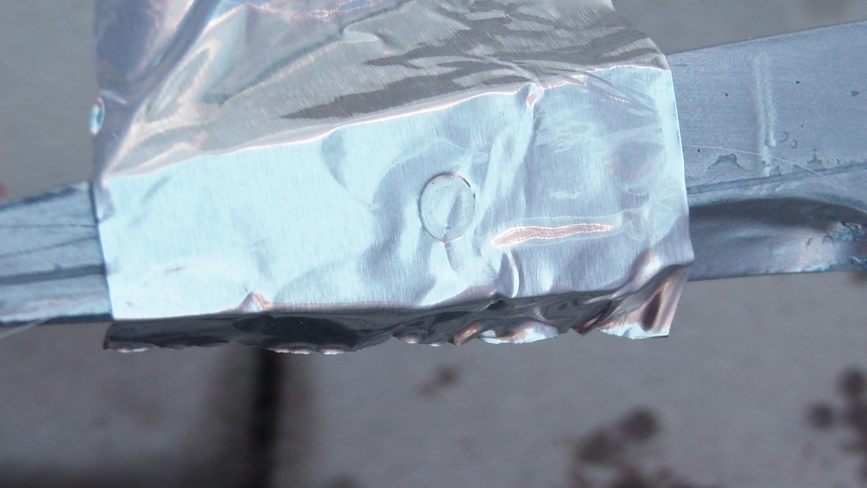
Slide the 5mm coal wing lock through the fuselage. Cover the wing root in the area of the lock device with alu tape, and attach the wing. If the wing is flush with the fuselage – it is best to check on the underside – press and twist the 5mm coal rod against the wing root to obtain an imprint.
Drill a hole for the rear wing lock with 5mm. Reapat all with the other wing.
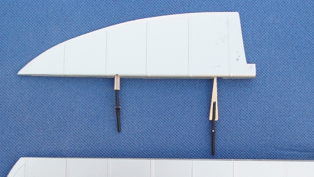
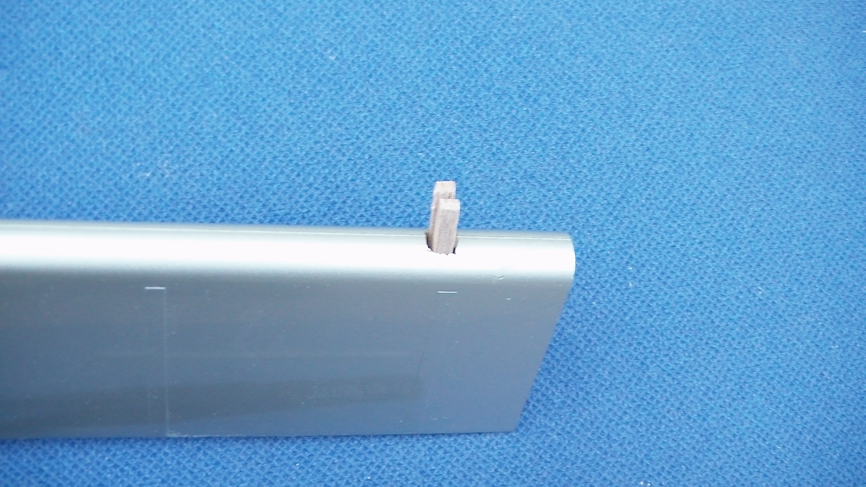
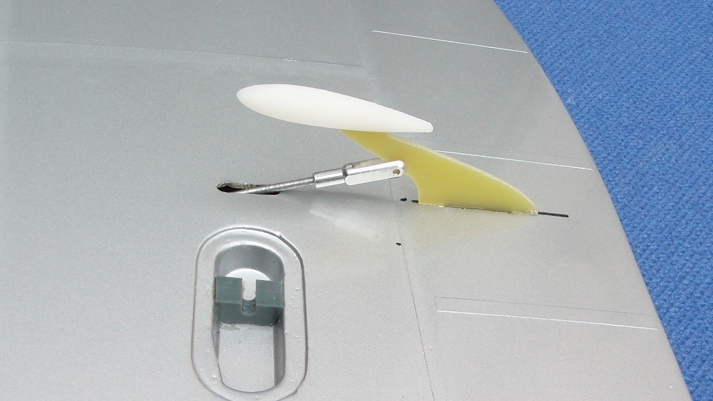
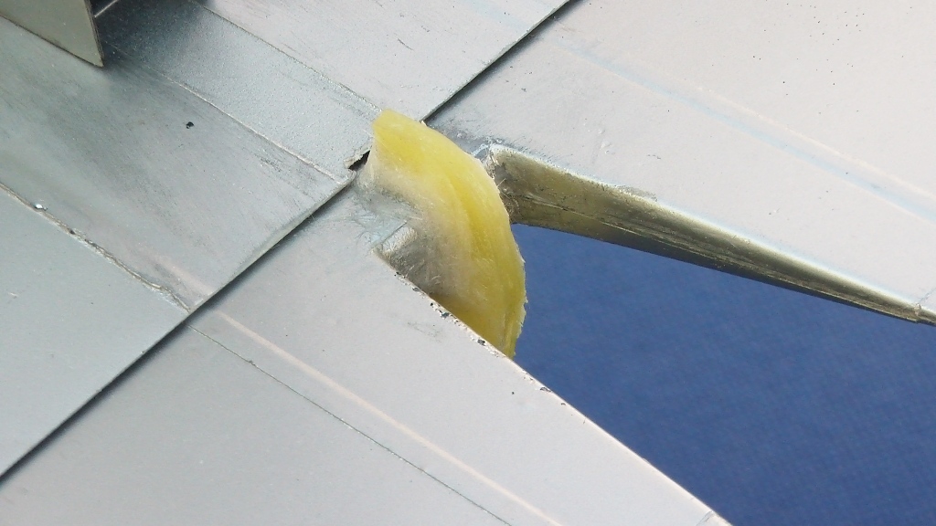
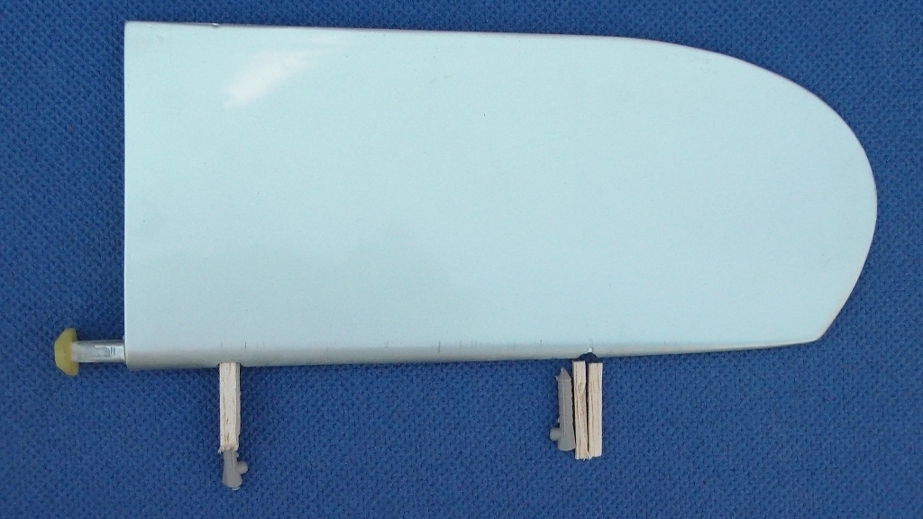
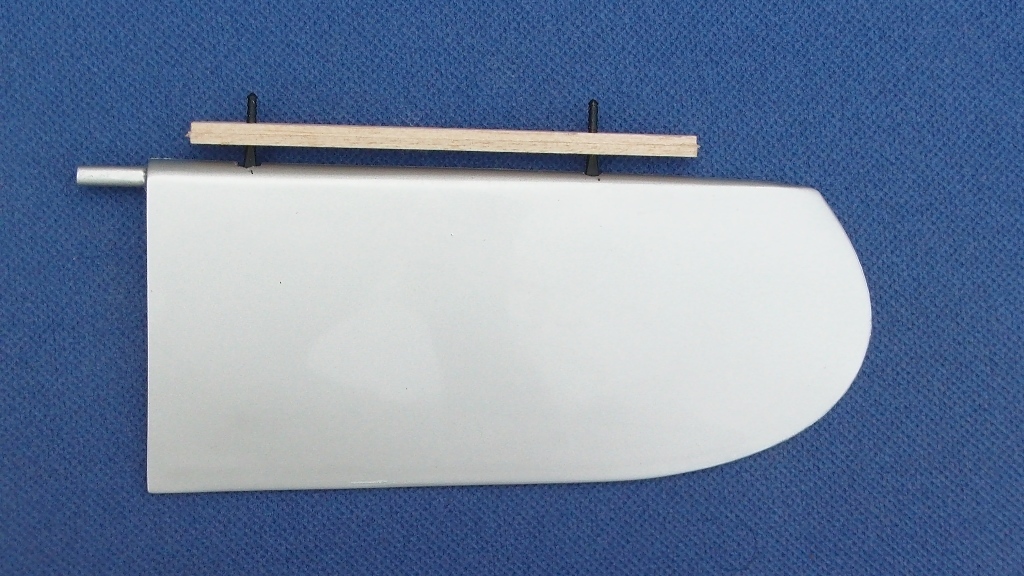
Elevator: At the points shown on the pic, make square openings about 6mm wide and 6mm high.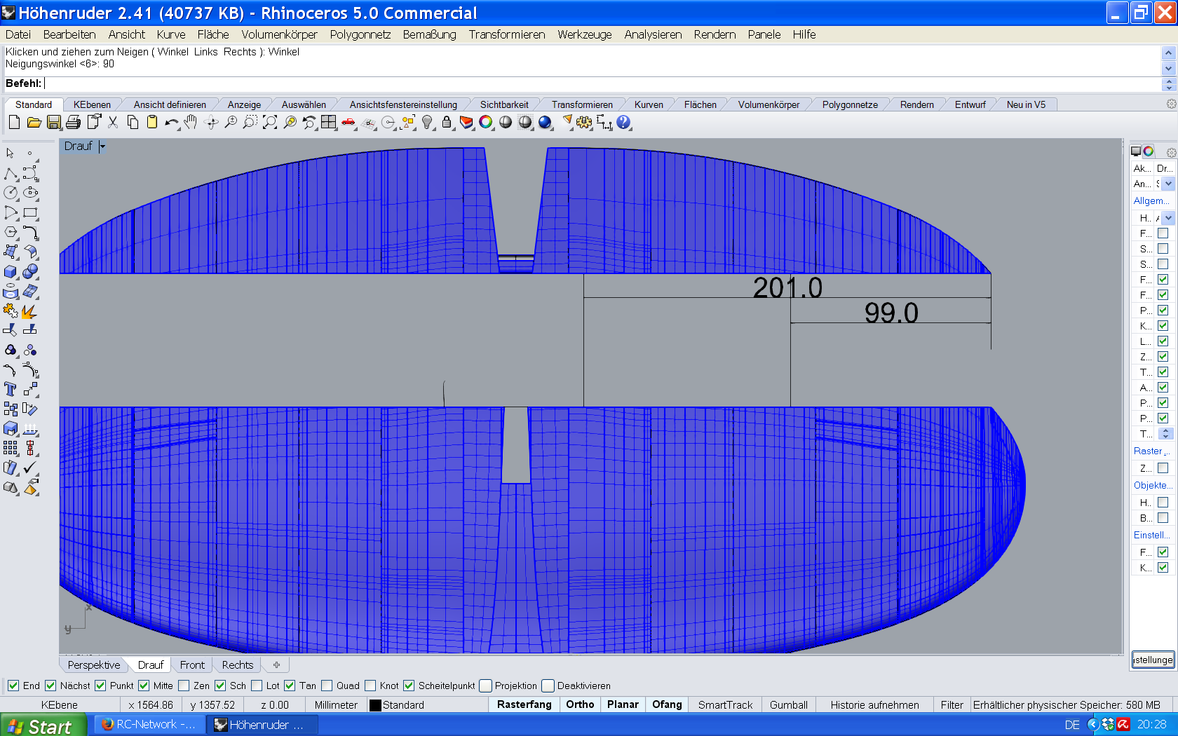
The hinge supports of plywood are inserted into the openings by pressing the hinges at the open end and pushing them in until the hinge supports reopen. Caution: Insert slowly and precisely at a right angle! Check if the 3mm pin hinges fit, the pin hinges must be shortened so that their joint is as deep as the respective radius of the leading edge. Do not glue the hinges yet, but remove them again, then glue the hinge brackets in place using Cyano that is placed in the openings. Then insert the pin hinges, hold the elevator fin to the elevator and mark the position of the pin hinges on the elevator. There drill 3mm holes exactly in the middle between upper and lower skin of elevator. Insert pin hinges, fix the joint precisely at the height of the end of the elevator trailing edge, and use a drop of Cyano. Just a drop in case you have to correct something. Connect the elevator and check whether sufficient deflection is possible upwards and downwards.
For the first flights, make the deflection 12 mm up and 10 mm down.
Elevator can now be glued onto elevator fin unless you will do some more painting.
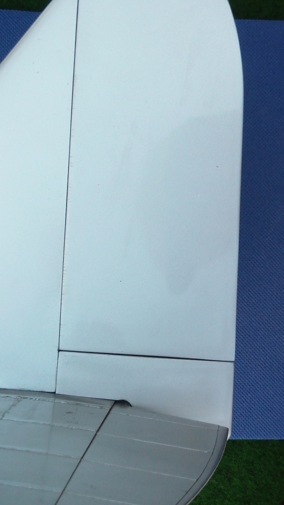
Use tape, preferably not too sticky to avoid any danger of ripping off paint, to protect elevator in the middle area in order to avoid scratching and insert into the opening at the end of the fuselage. Slide in carefully from the side. Adjust opening if necessary.
Attach the wing and measure the angle of incidence, this must be 1.3 degrees. Adjust elevator, measure for symmetrie with wingtips and check if parallel, and glue to fuselage with epoxy. Let the last 5cm of the right fuselage free of glue, as the bowden cable for the rudder runs there later.
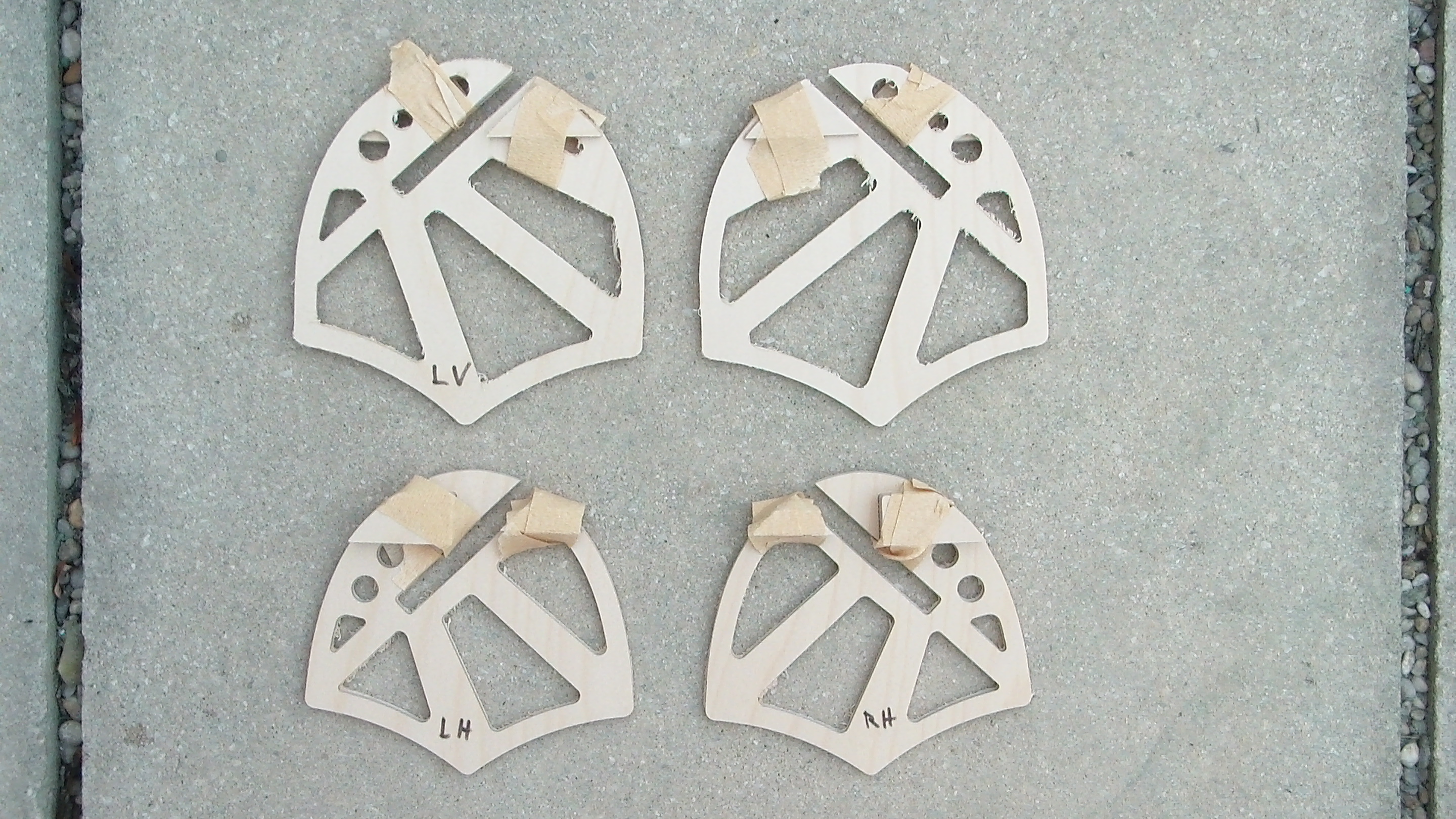
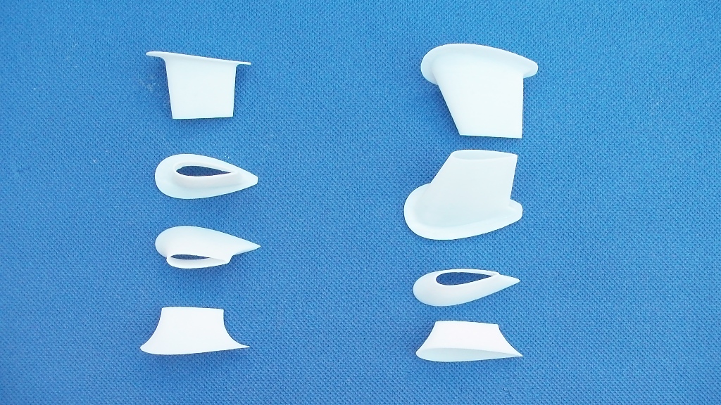
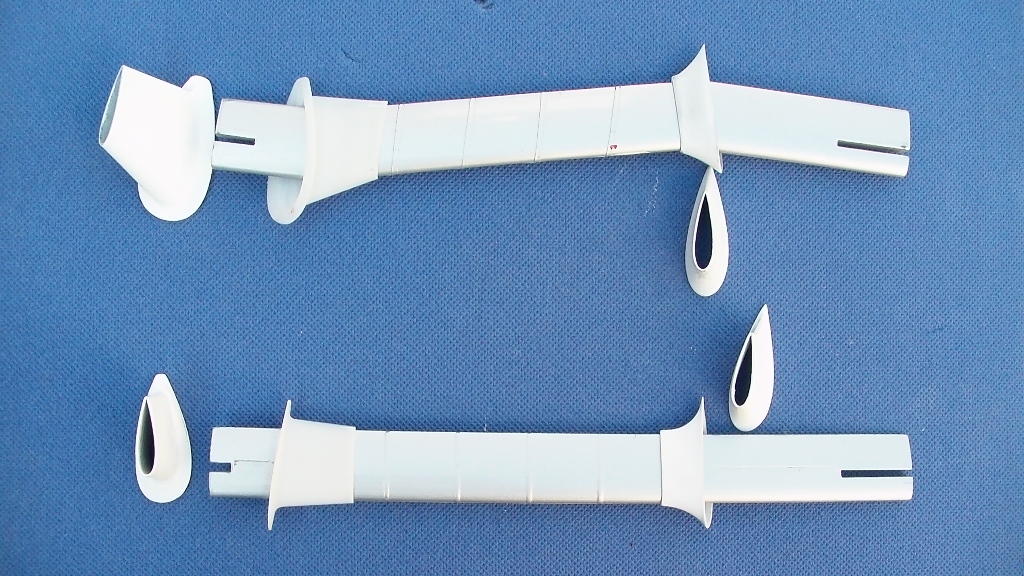
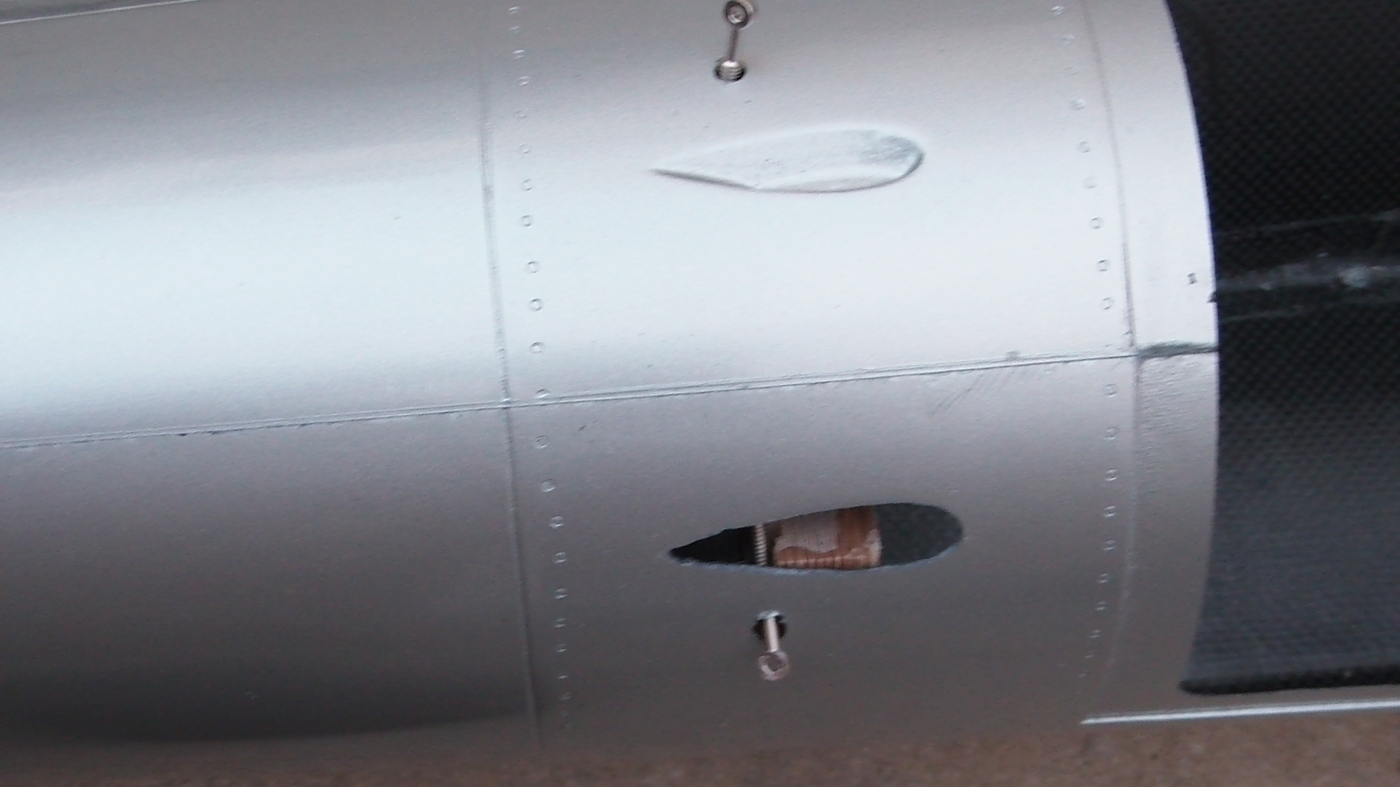
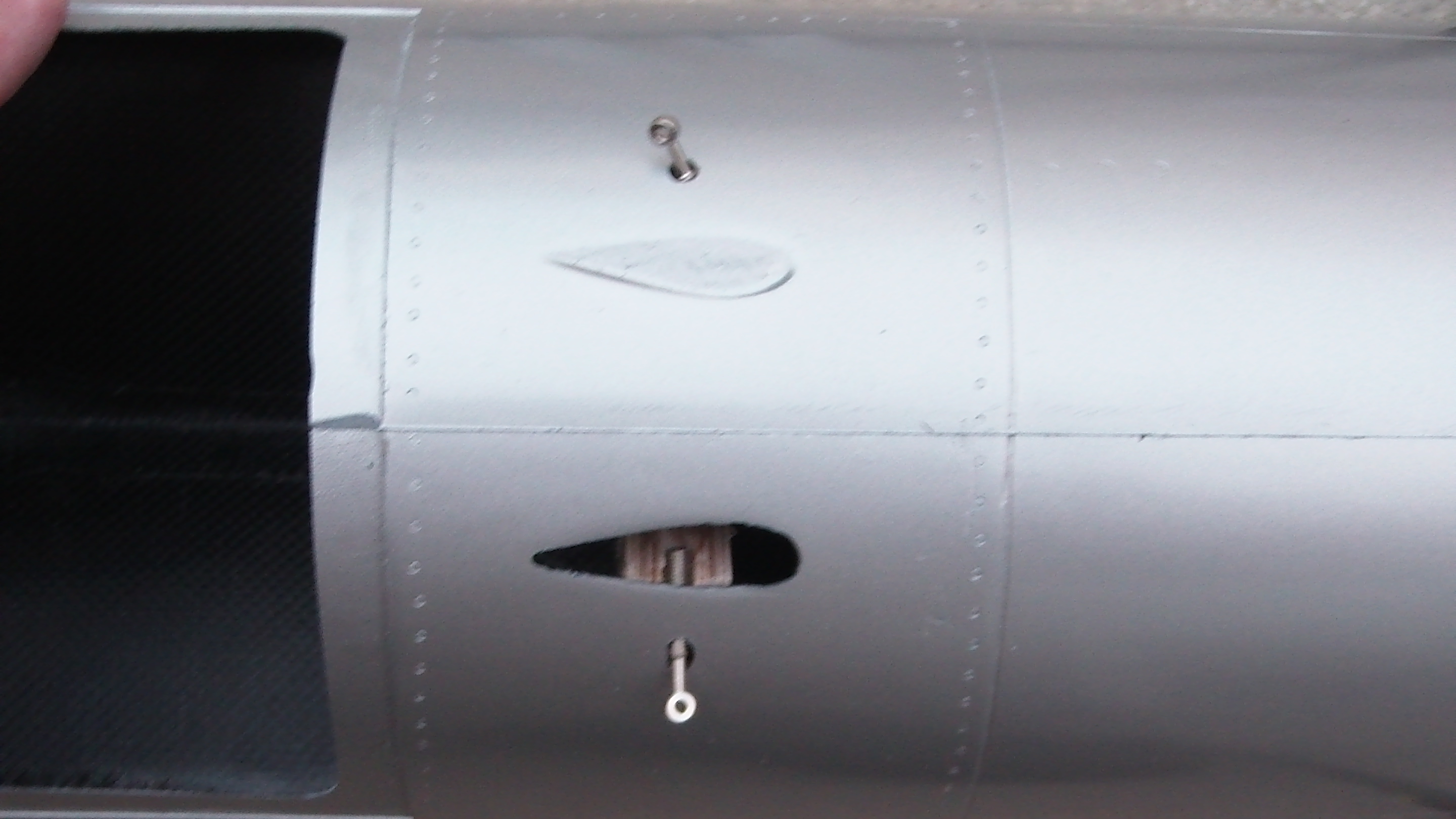
Floats. The best thing to do first is to work on the fillets between the struts and the fuselage and between the struts and the floats. The position on the photo corresponds to the position on the aircraft(i.e. left above,right below etc), fillets are shown in pairs.The lower rear fillets are smaller than the front fillets.
The fillets are made of ABS and have to fit tightly over the struts.
Trial fit over the struts
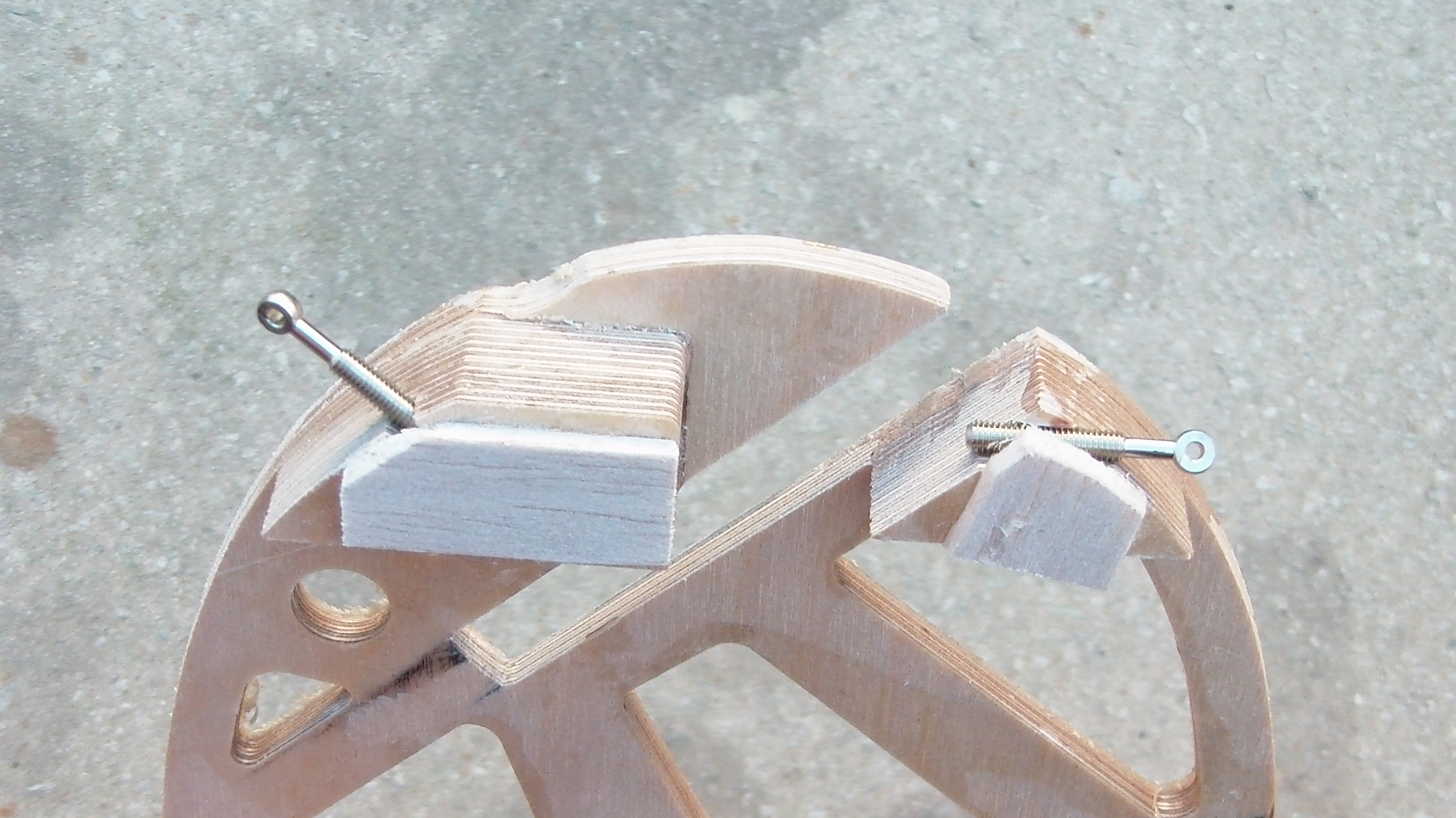
Now to the floats and their former: Glue the doubler to the former. These doublings create grooves, into which the eyebolts are glued later, when the former are in the floats.
Same with the rear former. Glue the blocks into the cutouts. Here in the picture the grooves have been designed with some balsa, but it is not absolutely necessary. The right eyebolt in the picture later points to the opposite float, the left forward and upwards to the wing.
Trial fit into the float former. The float struts must be able to be inserted into the former over the entire length without force exertion. If the slits have to be reworked in width, then remove them on both sides.
Place former into the floats.The blocks of the aft former point towards the end of the float, as do the doubling of the front former. Once again insert the float struts in floats + ribs, after the struts are now pushed in at an angle, the openings in the float may need to be slightly broadened.
When everything fits, remove float struts again and slide the lower fillets on the float struts. Insert struts. Place the former so that the openings of the grooves (2 each per frame) are aligned with the holes in the floats, preferably use the the eye bolts for checking.
The two eyebolts on the inside of the floats, which will later connect the floats together, lie horizontal. For this purpose, the opening in the floats may have to be reworked, resulting in an oval opening.
On the outside of the floats, where the eyebolts point towards the wing, the front eyebolt points rearward, the aft forward, exactly corresponding to the groove in the float. Seen directly from the front, the eyebolts are parallel and point slightly upwards.
Now insert float struts + floats into the fuselage. Evenly insert the front and rear float struts into the fuselage former to avoid canting.
Place the aircraft on the floats and measure. For the exact positioning of the float formers in the floats, use the eye bolts.
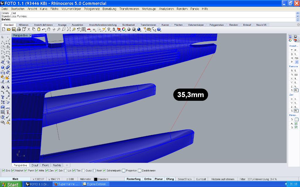
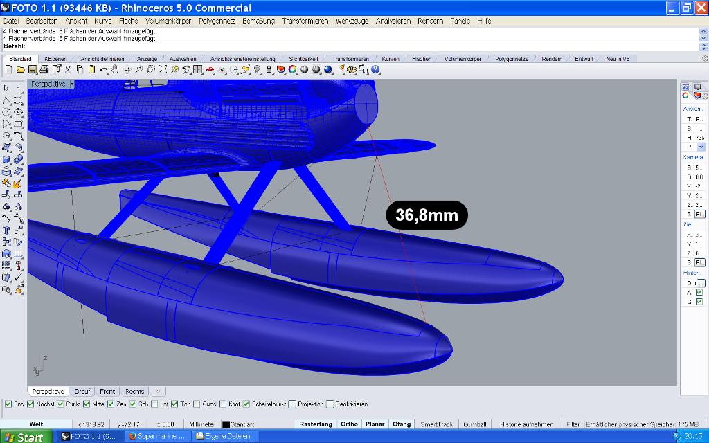
The distance of the floats must be 38 cm, use tape to fix. Distance lower center of the fuselage to the center of a float, where there is a doubling, 36.8mm. Distance from the fuselage (without rebate) to the center of the float, where the sheet doubling ends, 35.3mm Distance behind the fuselage (without rebate) to the center of the float, where the sheet doubling ends, 35.3mm.Attach wings and check for symmetrie and parallel to floats.
Now fix the former in the fuselage and floats with a little 5 minutes of epoxy resin. Also fix the float struts in the floats. Do not glue the float struts into the fuselage yet, so the model is better to handle for the next steps. Glue the eyebolts into the former. The inner ones, which stand opposite each other and connect the floats later on, must be inserted as far as possible, so far that the thick edge rests against the float.
Pull the float with the struts out of the fuselage, now the former can be glued properly with floats and struts. Where the struts exits the float, seal with epoxy or silicone. Therafter slide the fillet into place.
Now glue the fuselage former into the fuselage.
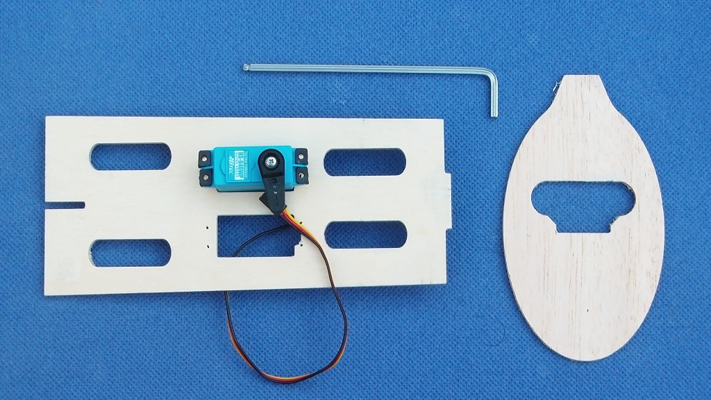
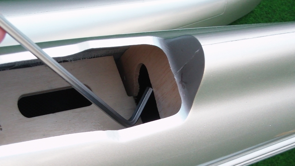
Drill holes for elevator and rudder servo into the servo mount. An allen key is helpful for installing the 3 mm balsa rib that is right behind the servomount.
The 3mm balsa former may have to be made narrower in the uppermost area, where it disappears behind the headrest.
The 3mm balsa former is simply placed in the back of the fuselage, below the headrest. Then insert the servomount into the front hatch and push at this angle backwards into the area of the cockpit opening, past the bracket, which later takes up the pylon for the bracing. Then turn the servomount into the horizontal and insert it with the front slot into the pylon holder.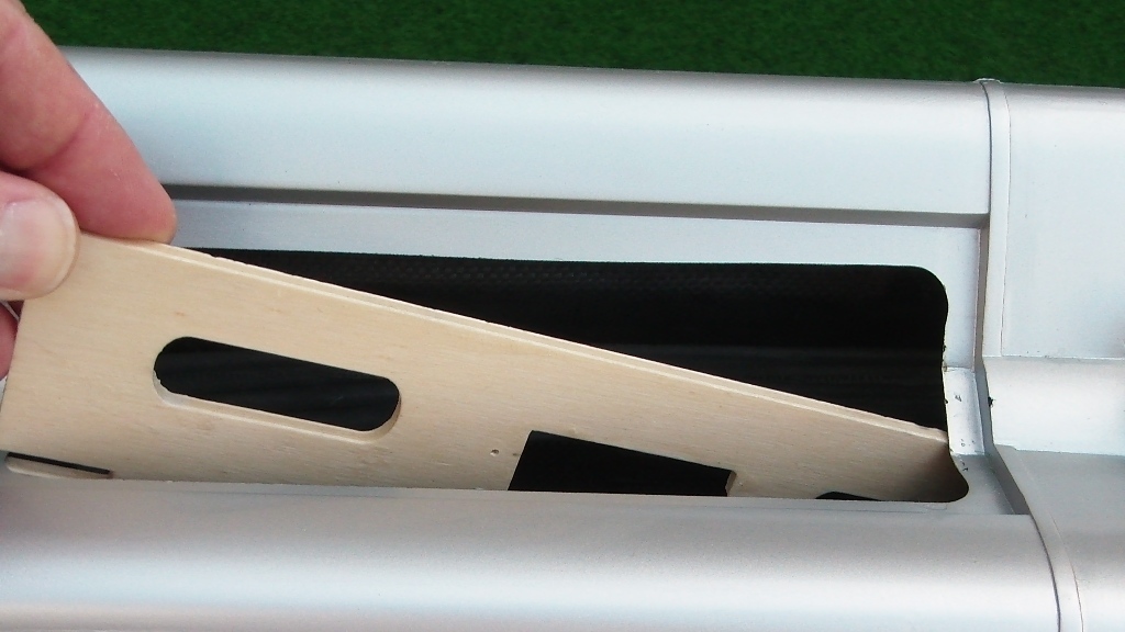
Now use the allen key to move the 3 balsa and straighten it. Use the 6mm carbon rod (which is the pushrod for the elevator), insert from the back of the fuselage and push the 3mm balsa former carefully in place. The servomount must engage in the 3mm balsa former.
Glue the servomount 5cm at its front and rear ends to the fuselage side wall. Likewise, the tube for the tube for the alu connector can now be glued permanently. Glue the 3mm balsa former to the fuselage.
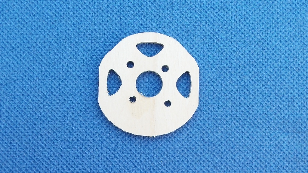
The motor hold is then glued in. It has to lie flush on the front of the fuselage, depending on the radius of the lamination, the front edges have to be rounded slightly. Screw the engine onto the holder, place both in the fuselage, place the appropriate spinner on the motor shaft to place the everthing exactly in the center. Fasten with 5 minutes epoxy, then remove the engine and glue the hold fully with epoxy and glass fiber cuttings.
Ailerons
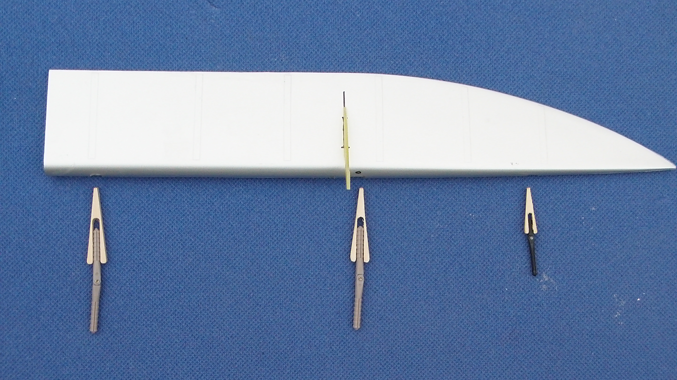
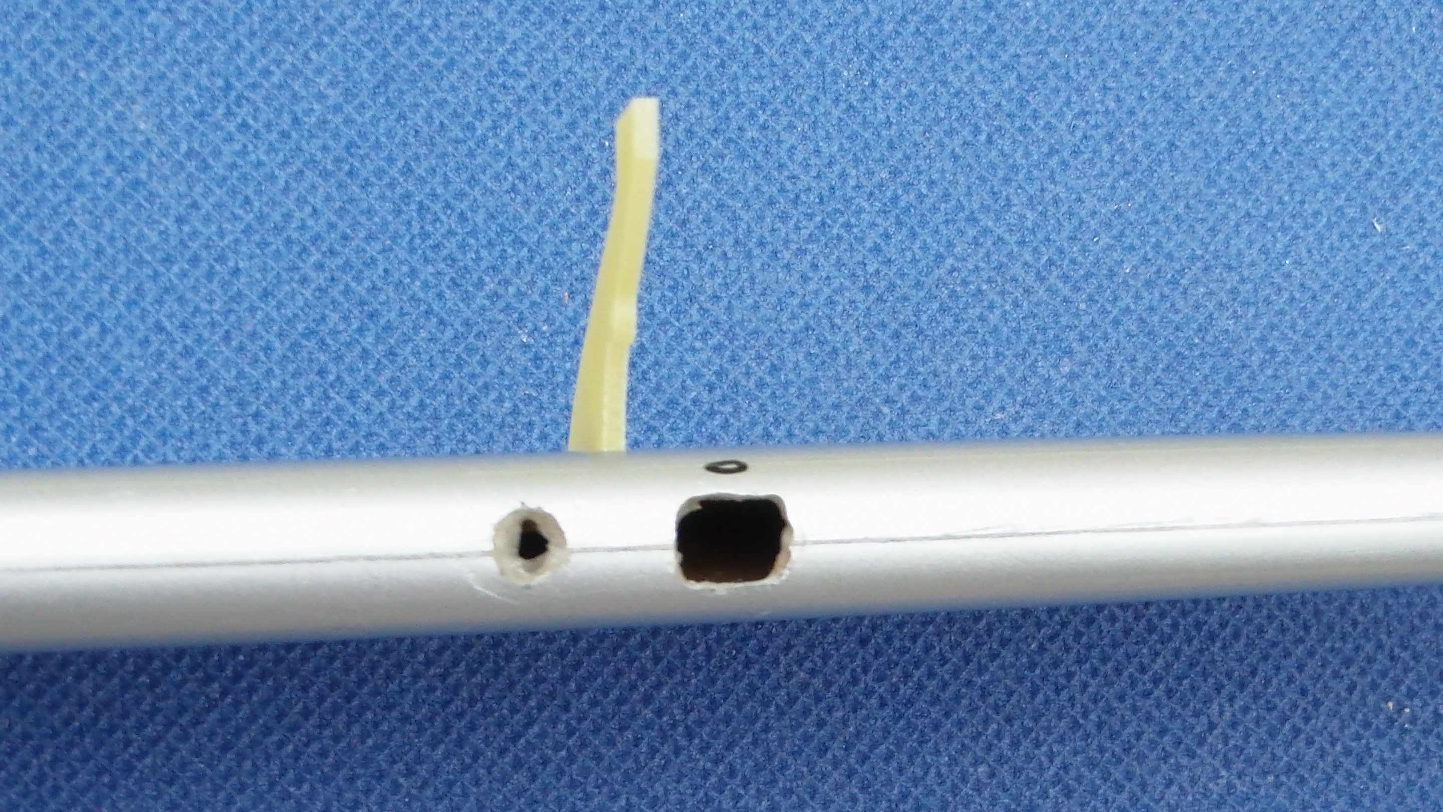
In the leading edge of each aileron drill 3 square openings each. From left to right in 32mm, 172mm, and 306mm distance, respectively, measured from the left edge of the aileron. The two first openings 9mm wide and 8mm high, the outermost opening 8mm wide and 6mm high. There are two 6mm pin hinges and a 3mm pin hinge on the outside.
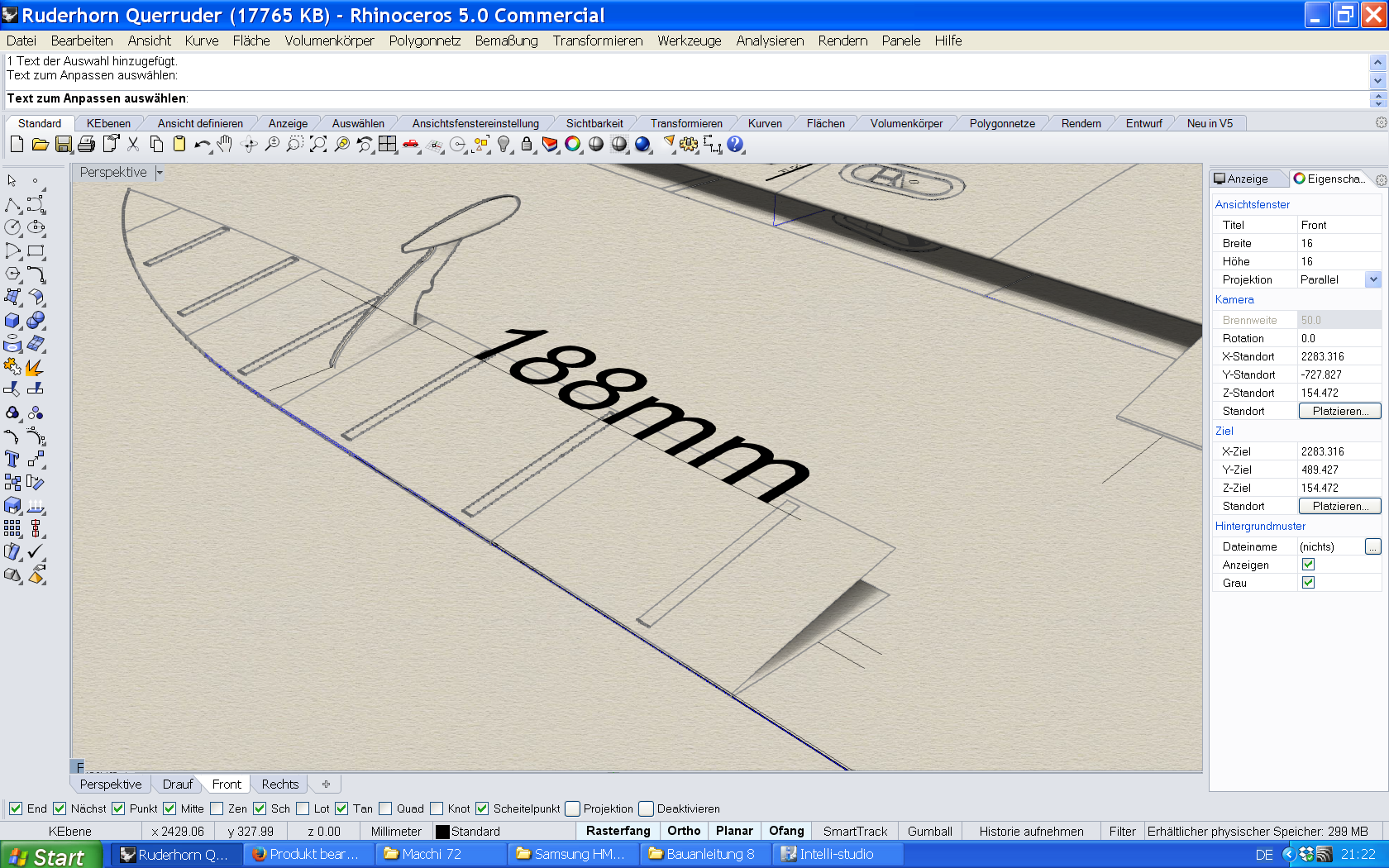
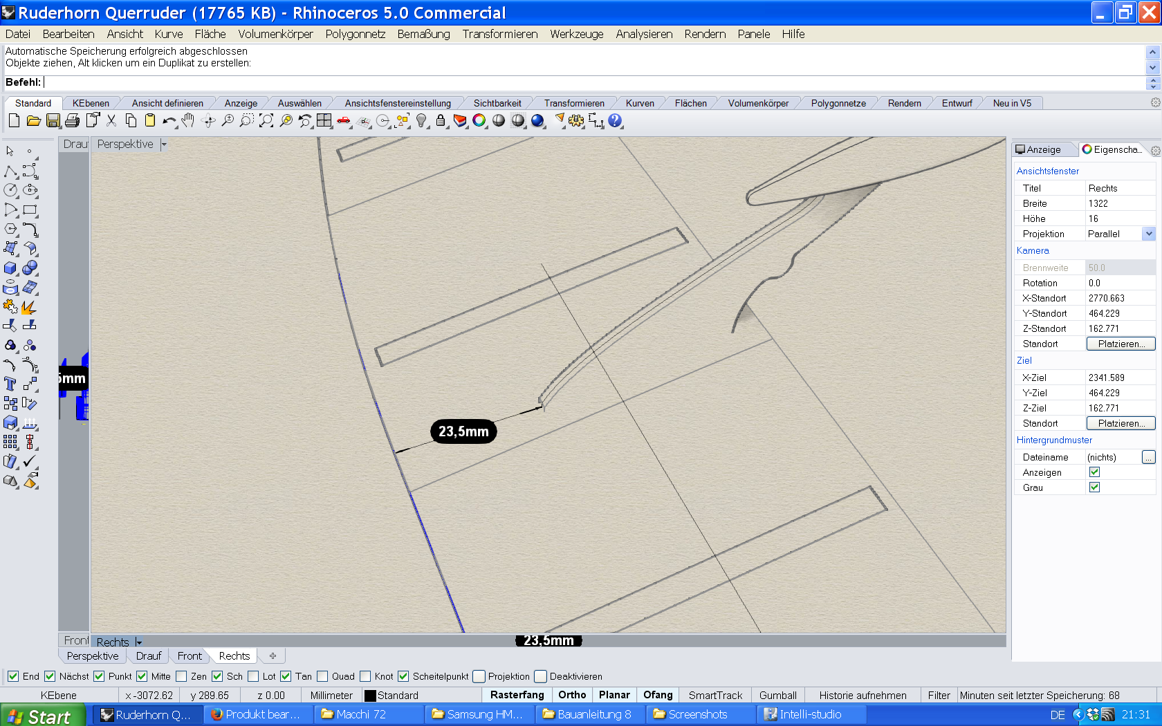
For the control horn, cut a 2mm wide slot. Distance from the edge the aileron 188mm, distance of the control horn from the rear edge of the aileron 23,5mm. Caution: make the slot only 18mm long, corresponding to the pin of the rudder horn
Fit control horn in a right angle. In addition to the opening for the pin hinge, drill a hole so that the control horn is accessible from both sides for gluing and glue with both the top and bottom of the aileron.
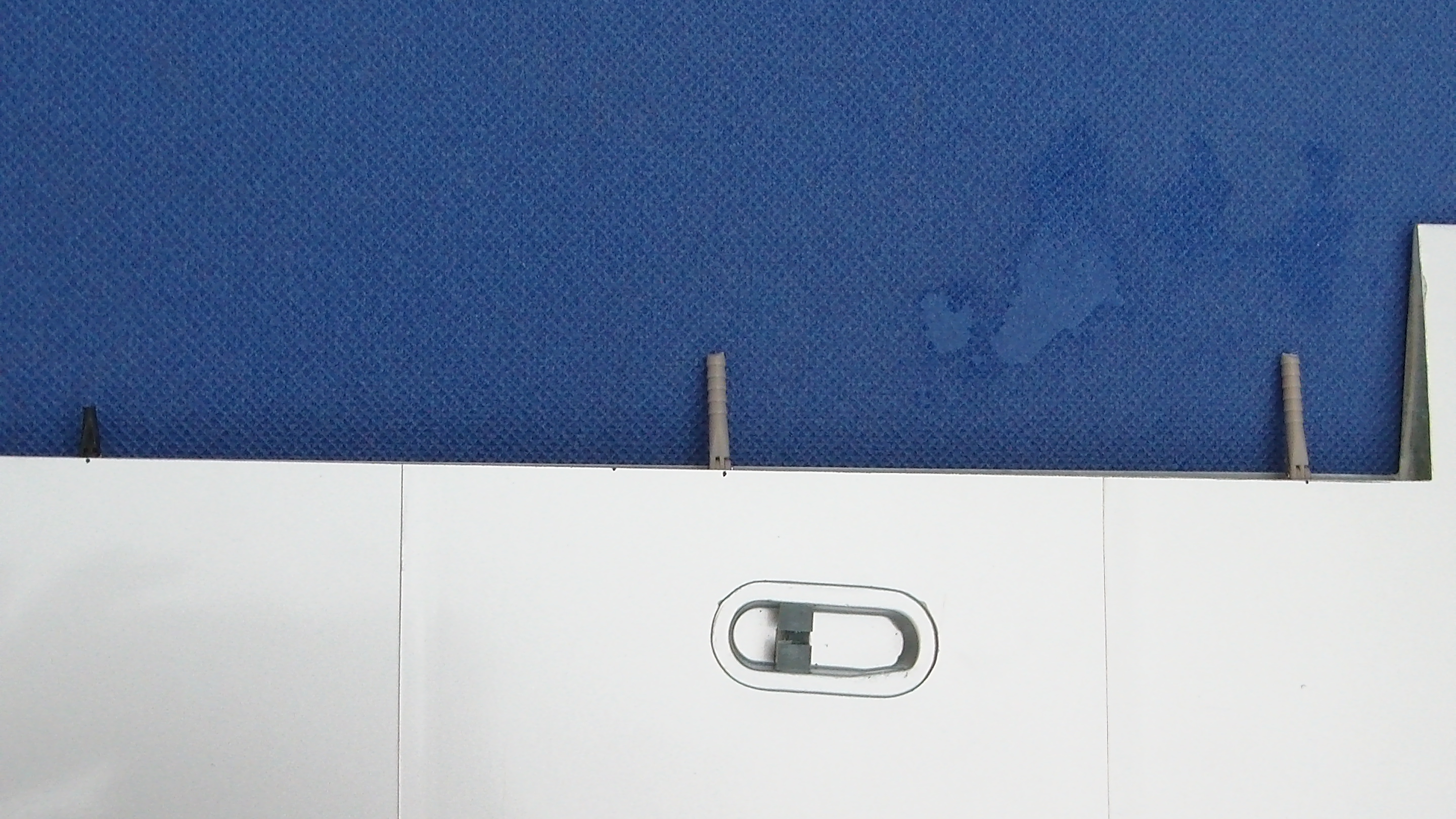
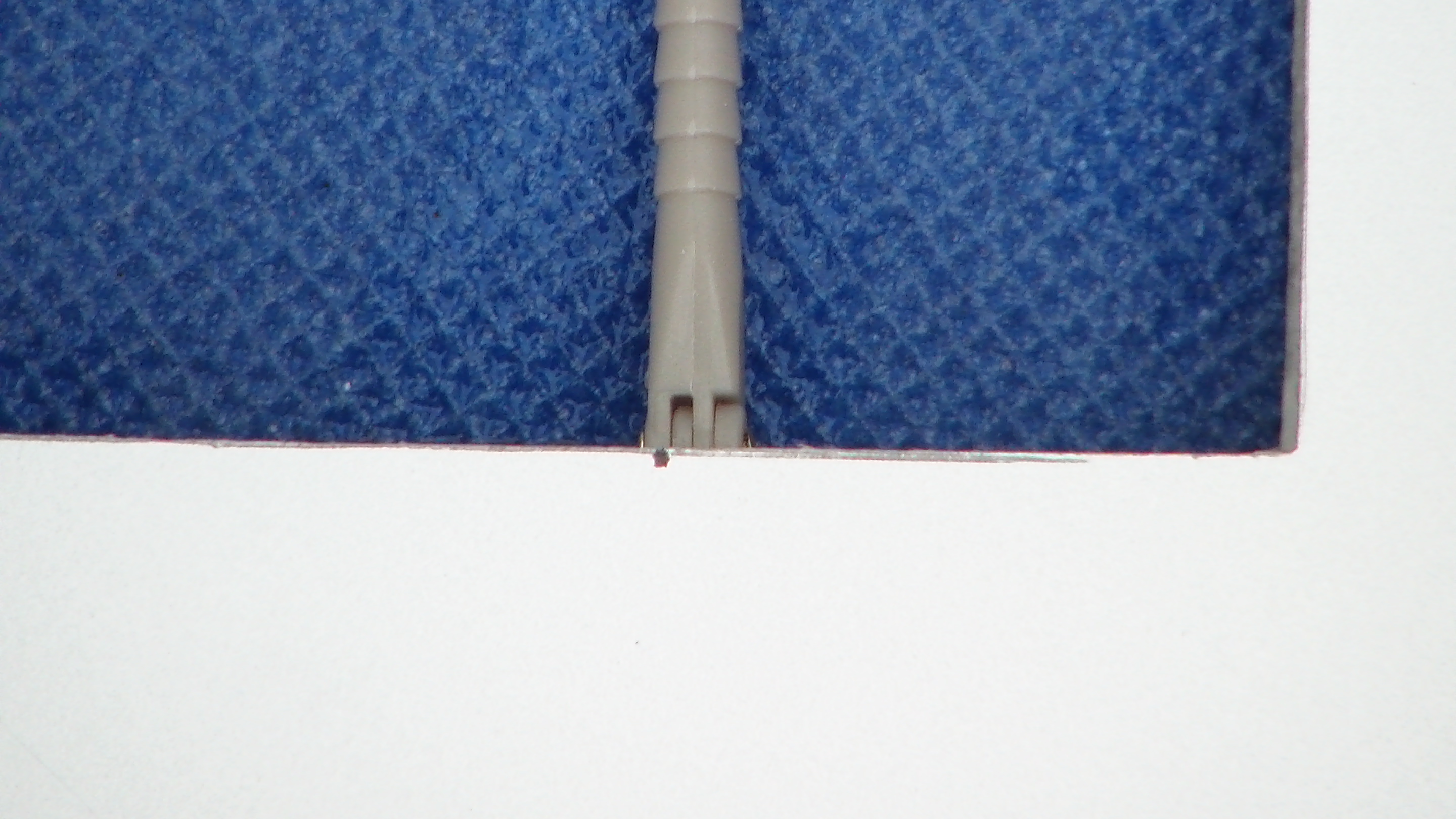
Insert the holder for the pin hinges. Insert the holder straight and carefully, pressing the open ends together. Push as far as the holder opens again. The pin hinges themselves must be slightly shortened, so that the center of rotation is about the radius of the leading edge behind the leading edge. Then trial fit the pin hinges. Pull the hinge pin out again and glue the holder with Cyano.
Insert pin hinges, do not glue! and check for right angles.Position aileron to the wing and mark positions of the hinges. Drill holes at marked positions, right in the middle between upper and lower skin of the wing.
Insert pin hinges into the holes of the trailing edge of wing. The hinge line exactly between the upper and lower wing skin, the hinge center in the middle between the wing skins. Check for right angles. Use a drop of Cyano to fix the hinges. Attach ailerons and check for proper deflection. If everthing fits use epoxy to glue hinges permanently into place.
Ailerons can now glued into place unless you want to paint them.
For the first flight, use 12 mm up deflection, and 10 mm down.
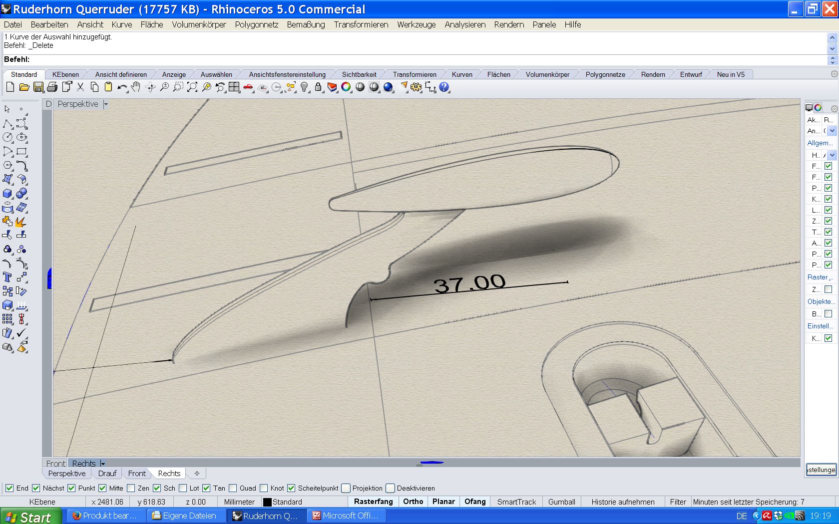
For the aileron linkage drill a hole at the height of the control horn 37mm in front of the wings trailing edge (37mm without aileron.) Drill with 3mm und make a slot to both sides with 17mm length.
Place servo for aileron so that an approx. 9mm long lever arm comes to lie about 7mm under the wing shell. Due to the big variety of servos there are no parts for aileron installation in the kit. Here, the servos were screwed on plywood boards, these boards are glued to the wing shell on balsa blocks. In any case make shure that there is big glueing area from servo to the wing skin!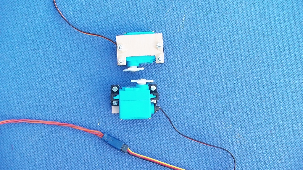
Linkage is screwed to the fork head on one side, glued to the fork head on the other side.
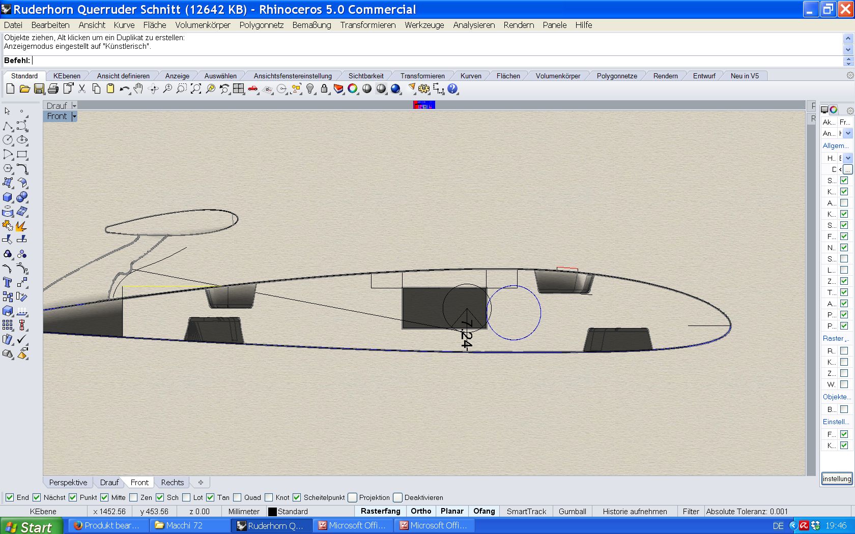
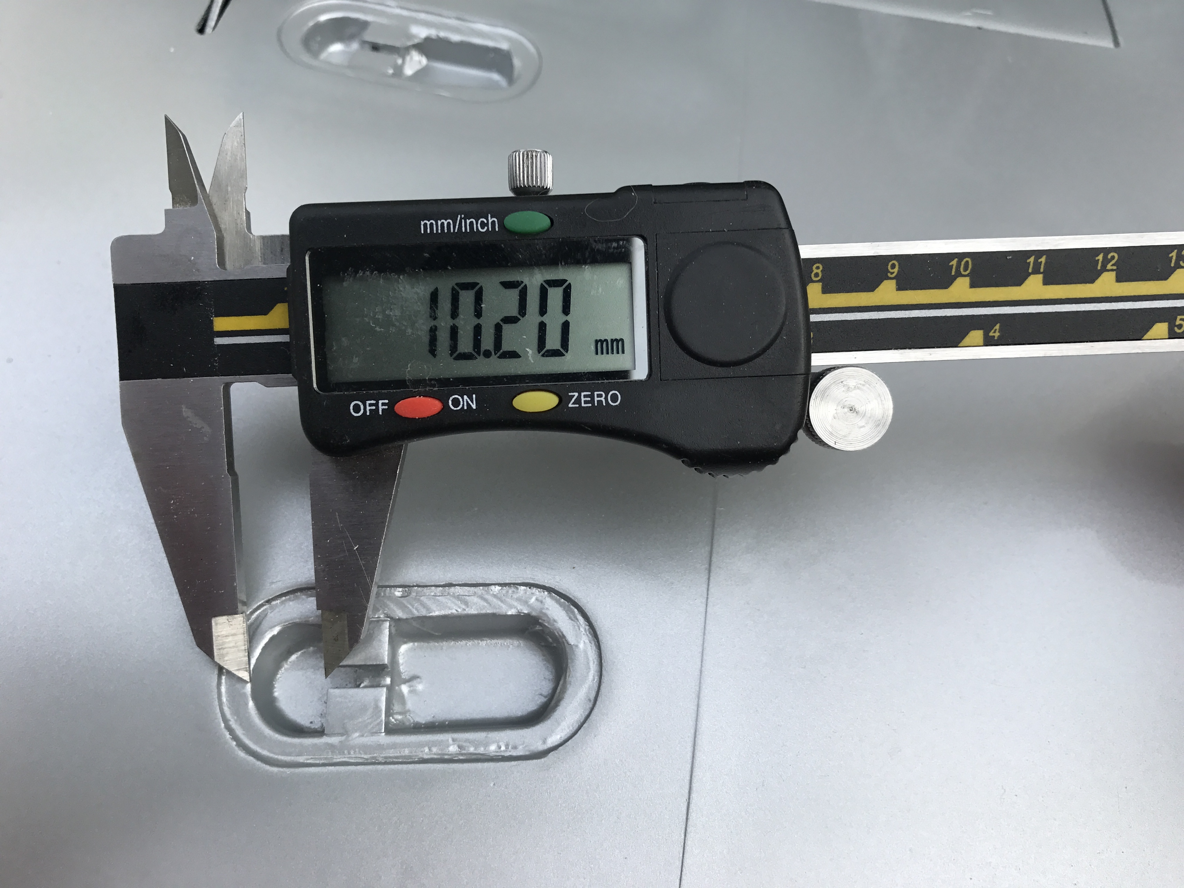
Next, the plastic blocks holding the wing struts are glued. Blocks are mad of hard PVC and can be glued with epoxy. Measure as shown in the pic, measure always from wingtip inwards, means the wingtip on the pic is on the left side.
Front upperside: 10,2 mm.
Rear upperside: 11,2 mm.
Front underside: 10,5 mm.
Rear underside: 17 mm.
Measure always from to the wingtip inwards, on the pic the wingtip is on the left side. Measure as shown from the inner edge from the hutch to outermost part of the PVC block.
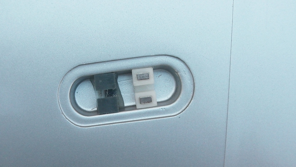
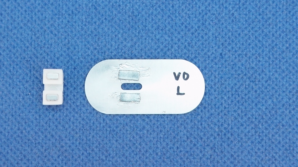
Right aside the blocks, in each case on the side facing the fuselage, lid holders are glued. Place two magnets in each of the printed caps, use one drop of Cyano glue and then carefully press the magnet with pliers.
Glue two iron strips onto the alu lid.
Use Epoxy or Polymer glue. The distance and the position of the iron strips so that they come to lie on the magnet. Then put the alu lid together with the lid holder into the hutch so that the correct position can be checked. If everything fits, glue the lid holder with epoxy.
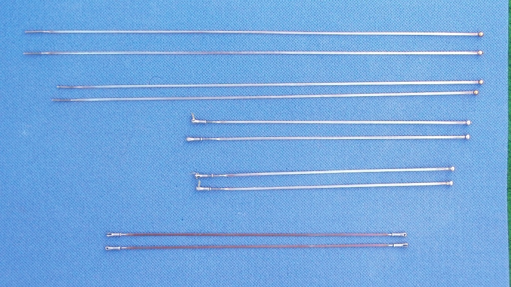
The wing struts are in one piece. The struts between the floats are specially marked and also identified by a left and a right thread at each end.
Secure the float struts between the floats to the eyebolts using a bolt and securing pin.
Cut the wing struts in half in the middle.
The longest brace is on the top front. The second longest on the top rear.
On the underside the front strut is longer than the rear.
The plastic part of the pylon has inserted threads, the plastic part must be glued to the wooden part. Place pylon into fuselage, make shure that the backside faces rearwards. Screw the threaded end into the pylon in the fuselage for the upper struts, and by means of fork connections and bolts from the floats to the wings. Allow about 5-7mm of air to strain the struts later. Cut the struts, so that they lie between the plastic blocks in the sump, and glue a brass ball with epoxy. Attach all the bracing, and measure once more for correct position of wings and floats. Therafter glue pylon into place.
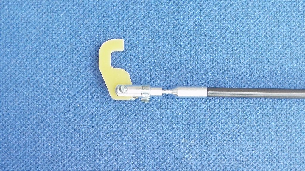
Glue control horn for elevator into place, right in the middle of the elevator. Sand away any paint to ensure a perfect bonding, use slow curing epoxy and some glas flakes.
Glue the alu connector to one side of the 6mm carbon rod, place it into control horn of elevator. Cut the other side to length to connect with elevator servo and glue the second alu connector in place. Sand carbon rod and clean to remove any release agent, use slow curing epoxy.
Rudder: Hold rudder at the its place to the fin and shorten the pin on the underside to allow for a few milimeters clearance with the elevator. Slide control horn over the pin.
The former that holds the pin hinges is made of two parts of balsa, glue together and make shure that the holes align. Insert two pin hinges into the holes, align for right angles. Place into the rear of the fin – make shure that the fin is not deformed in any way, neither forced apart nor squeezed. Hold rudder into place and mark the position of hinges. Drill holes at markings to insert the Robart pin holders, use some scrap balsa for filling, and use the balsa former with the inserted hinges as template to get the correct distance between hinges. Insert the holders together with the pin hinges to make shure the pin hinges are deep enough – the hinge joint mus be as deep as the radius of the leading edge of the rudder at the appropriate point.
To get a perfect fit now use the aft cone and put it into place together with the rudder. The aft cone needs openings for the pin below the rudder and for the control horn at the right side. Use the aft cone as benchmark – when the aft cone fits, the trailing edges of both must align, the rudder mus be straight and about half a millimeter play between rudder and aft cone.
Remove rudder again, check the balsa former together with hinges is still parallel to the leading edge of the rudder. Use a slow curing epoxy on both sides inside the fin (if you put it on the balsa former it will smear inside the trailing edge of the fin when inserting the rudder again, so put the glue inside the fin) and place rudder + aft cone into place again and align. Do not use any glue for the hinges yet.
Once the balsa former is in place, adjust hinges so that their joint is right at height of the end of the fin. Use a drop Cyano to fix and check position of rudder and deflection. When everything fits, glue hinges permanently into balsa former. If necessary, sand carefully inside the fin to remove any epoxy residuals that could prevent deflection. Deflection should be 30 – 35 mm each side.
Thereafter use the bowden cable to connect the rudder with the servo.
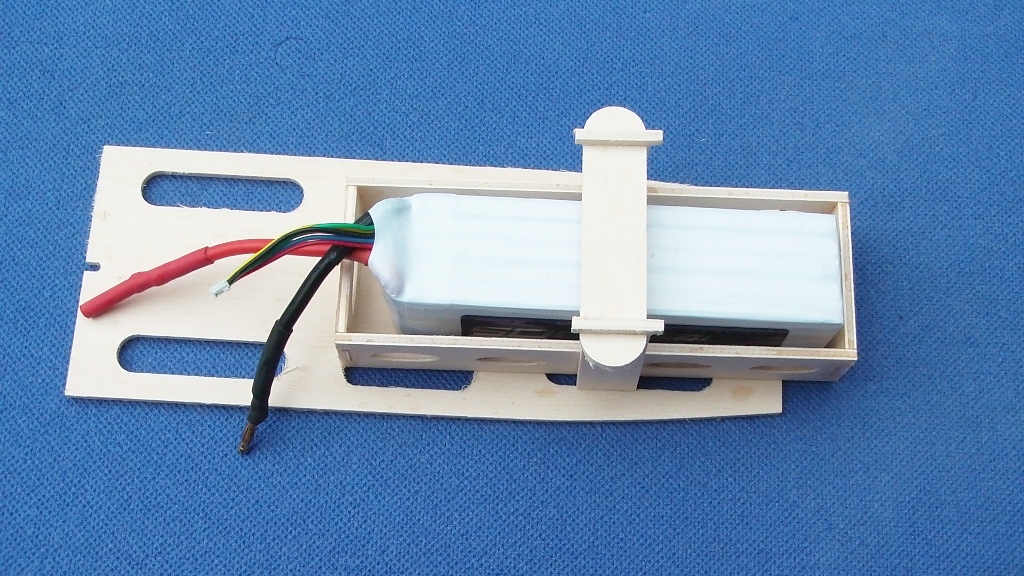
Then assemble the battery holder. Glue the battery support into the fuselage, and glue battery holder onto battery support.
Balance the plane to 80 mm behind leading edge. Use lead in the tips to achieve CG.
